Скіс – Bevel
Орієнтир – Reference
| Режим: | Режим Правки – Edit Mode |
|---|---|
| Меню: | |
| Скорочення: | Ctrl-B |
| Меню: | (vertex-only) |
| Скорочення: | Shift-Ctrl-B (лише вершини) |
The Bevel tool allows you to create chamfered or rounded corners on geometry. A bevel is an effect that smooths out edges and corners.
Ребра, краї у реальному світі дуже рідко є точно гострими. Навіть ребро леза ножа не можна вважати ідеально гострим. Більшість ребер є навмисно скошені з механічних або практичних причин.
Скоси також корисні для надання реалізму не-органічним моделям. У реальному світі затуплені ребра на об’єктах ловлять світло та змінюють відтінення навколо країв. Це дає монолітний, реалістичний вигляд на противагу не-скошеним об’єктам, які можуть виглядати надто ідеально.
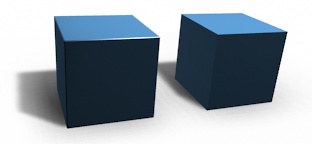
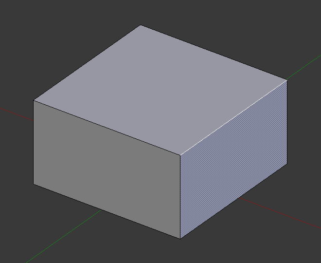
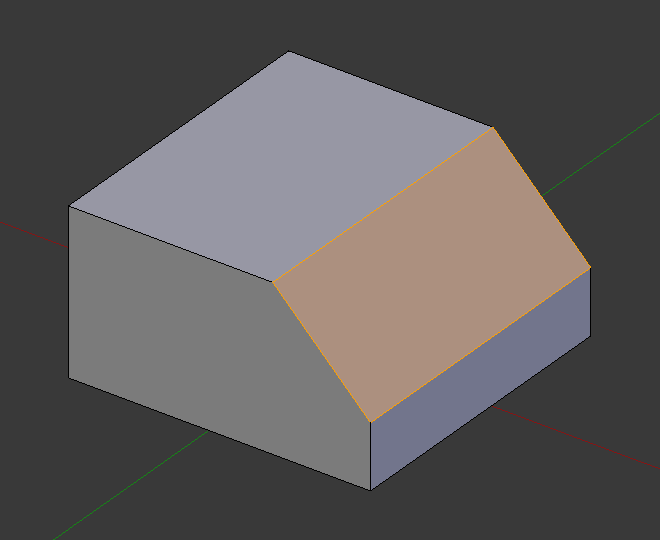
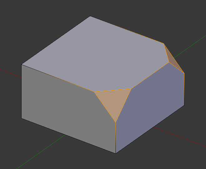
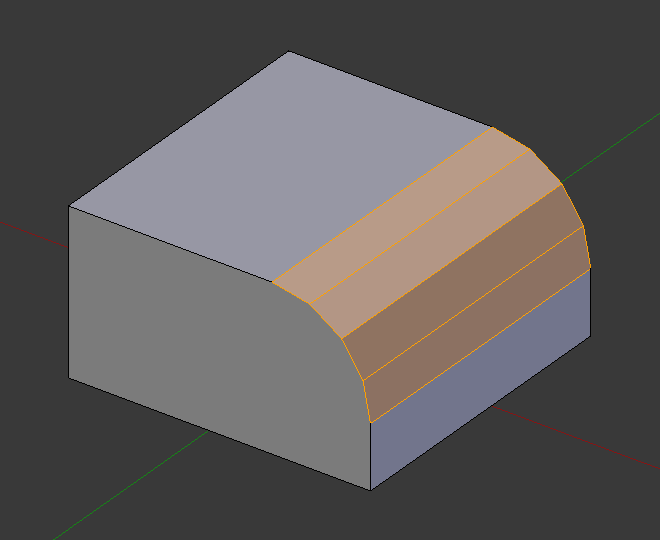
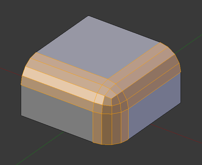
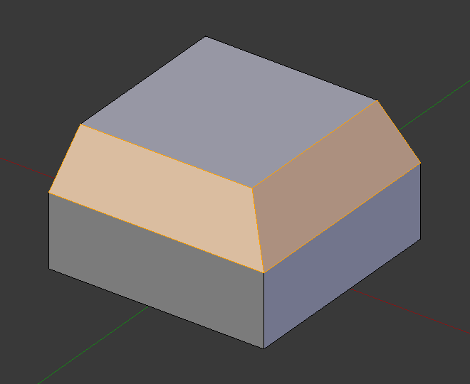
Куби зі та без скосу.
Використання
The Bevel Edges tool works only on selected edges with exactly two adjacent faces. It will recognize any edges included in a vertex or face selection as well, and perform the bevel the same as if those edges were explicitly selected. In «vertex only» mode, the Bevel Vertices tool works on selected vertices instead of edges, and there is no requirement about having any adjacent faces. The Bevel tool smooths the edges and/or «corners» (vertices) by replacing them with faces making smooth profiles with a specified number of segments (see the options below for details about the bevel algorithm).
Use Ctrl-B or a method listed above to run the tool. Move the mouse to interactively or type a number to specify the bevel offset, and scroll the Wheel to increase or decrease the number of segments (see below).
Примітка
Звичайне скошування (на ребрах) працює тільки на ребрах, що мають точно дві грані, прикріплені до них. Скошування на вершинах немає такого обмеження.
Опції
- Amount A
- Ви можете змінювати величину скосу, рухаючи мишею до або від об’єкта, дещо подібно як і для засобів трансформування. Точний зміст значення залежить від опції Amount Type (дивіться нижче). Як і звичайно, масштабування може контролюватися більш точними мірками шляхом утримування натисненою Shift для масштабування кроками по 0.001. LMB фіналізує операцію, RMB або Esc скасовує дію.
- Тип Величини – Amount Type M
Дає змогу обрати те, як значення Amount керуватиме розміром скосу. Відповідно до виділення, величина може бути:
- Зсув – Offset
- Відстань від нового ребра до оригінального.
- Ширина – Width
- Ширина грані скосу.
- Глибина – Depth
- Відстань перпендикулярно від оригінального ребра до грані скосу.
- Відсоток – Percent
- Відсоток довжини суміжних ребер, по яких ковзатимуть нові ребра.
For vertex-only bevels, the Offset and Depth types measure from the original vertex, and the Width type is measured from a new vertex to the center of the new face (as half the amount).
- Сегменти – Segments S
Кількість сегментів у скосі може визначатися шляхом прокрутки коліща Wheel миші для збільшення або зменшення цього значення. Чим більша кількість сегментів, тим згладженіший скіс. Або натиском S для зміни кількості за допомогою пересувів миші, а також числовим уводом.
Альтернативно, ви можете вручну уводити числове значення сегментів при використанні цього засобу або на панелі Mesh Tool після його використання.
- Профіль – Profile P
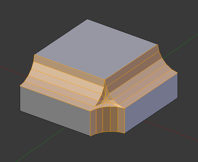
- Це число між 0 та 1, що керує формою профілю (боковий огляд скошеного краю). Стандартне значення, 0.5, дає кругову дугу (якщо грані стикаються під прямим кутом). Значення, менші, ніж 0.5, даватимуть плоскіший профіль, з 0.25 – це буде точно плоский, а значення менші за 0.25 даватимуть угнутий скіс. Значення, більші за 0.5, даватимуть більш випуклий профіль. Подібно як і з Segments воно може задаватися, використовуючи пересуви миші та числовий увід після перемикання за допомогою P.
- Лише Вершина – Vertex Only V
- При увімкненні цей інструмент буде у режимі «лише вершини» і скошування буде відбуватися тільки на вершинах.
- Затиск Перекриття – Clamp Overlap C
- Limits the width of each beveled edge so that edges cannot cause overlapping intersections with other geometry.
- Ковзання Петлі – Loop Slide
- Якщо є нескошені ребра уздовж скошених ребер на вершині, то скіс намагатиметься ковзати уздовж цих ребер, при можливості. Вимикання цієї опції може призвести до більш рівномірної ширини скосу.
- Mark Seams U
- If a seam edge crosses a non-seam one and you bevel all of them, this option will maintain the expected propagation of seams.
- Mark Sharp K
- Similar to Mark Seams, but for sharp edges.
- Матеріал – Material
- Число Material вказує, який матеріал повинен бути призначений на нові грані, створені засобом Bevel. При стандарті, -1, матеріал буде успадковуватися від найближчої наявної грані («найближче» може бути дещо неоднозначним). Інакше, дане число – це індекс гнізда матеріалу, що буде використовуватися для усіх ново створених граней.
- Harden Normals H
- When enabled, the per-vertex face normals of the bevel faces are adjusted to match the surrounding faces, and the normals of the surrounding faces are not affected. This will keep the surrounding faces flat (if they were before), with the bevel faces shading smoothly into them. For this effect to work, custom split normals need to be enabled, which requires Auto Smooth to be enabled (see Normals). As a convenience, that option will be enabled for you if it is not already when you enable Harden Normals here.
- Face Strength Mode
Set Face Strength on the faces involved in the bevel, according to the specified mode. This can be used in conjunction with a Weight Normals Modifier (with the Face Influence option checked).
- None
- Do not set face strength.
- New
- Set the face strength of new faces along edges to Medium, and the face strength of new faces at vertices to Weak.
- Affected
- In addition to those set for the New case, also set the faces adjacent to new faces to have strength Strong.
- All
- In addition to those set for the Affected option, also set all the rest of the faces of the model to have strength Strong.
- Outer Miter O
A miter is formed when two beveled edges meet at an angle. On the side where the angle is greater than 180 degrees, if any, it is called an outer miter. This option specifies the pattern that Blender uses at an outer miter.
- Sharp
- Edges meet at a sharp point, with no extra vertices introduced on the edges.
- Patch
- Edges meet at a sharp point but in addition, two extra vertices are introduced near the point so that the edges and faces at the vertex may be less pinched together than what occurs in the Sharp case. The Spread slider controls how far the new vertices are from the meeting point.
- Arc
- Two vertices are introduced near the meeting point, and a curved arc joins them together. The Spread slider controls how far the new vertices are from the meeting point. The Profile slider controls the shape of the arc.
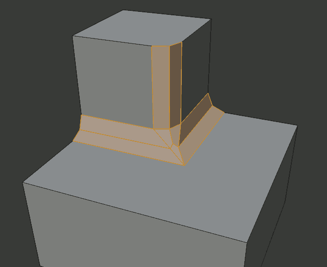
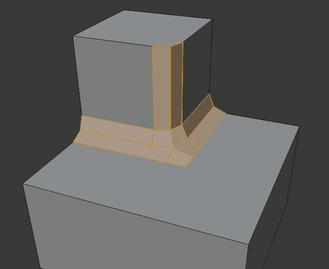
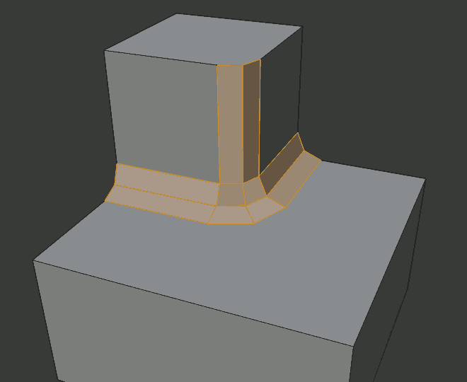
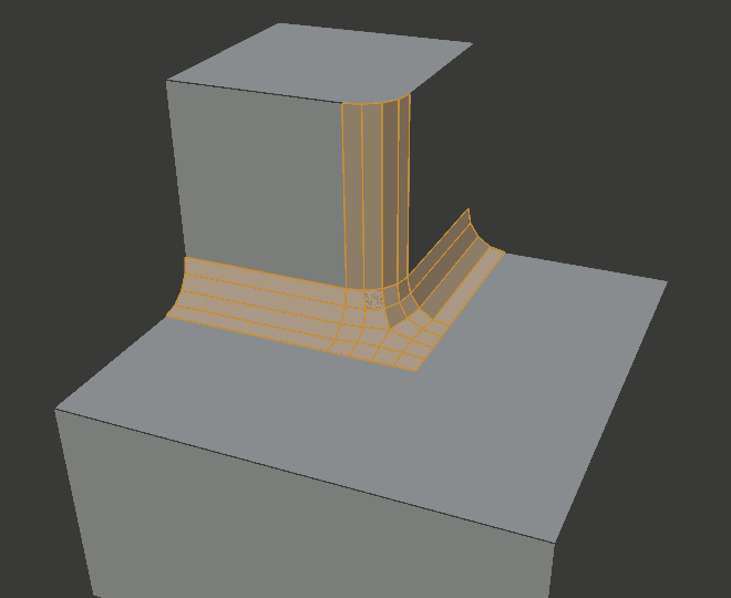
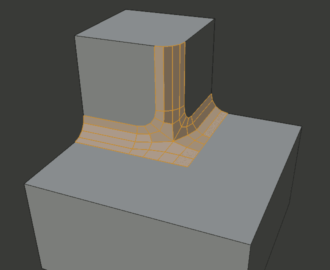
The current choices are shown in this diagram, where the outer miter is along the horizontal surface.
- Inner Miter I
An Inner Miter is formed when the angle between two beveled edges is less than 180 degrees. This option specifies the pattern Blender uses at an inner miter. The options are the same as for Outer Miter, except that Patch makes no sense and is therefore omitted. Inner miters are shown in the following diagram, where two inner miters are on the vertical surfaces.
- Spread
- The value used to spread extra vertices apart for Outer and Inner Miters.
Приклади
Дивись також
Модифікатор «Скіс» – Bevel Modifier
Модифікатор «Скіс» – Bevel Modifier – це не-руйнівна альтернатива інструменту Bevel.
