Модифікатор «Скіс» – Bevel Modifier
The Bevel modifier bevels the edges of the mesh it is applied to, with some control of how and where the bevel is applied to the mesh.
It is a non-destructive alternative to the Bevel Operation in Edit Mode.
Опції
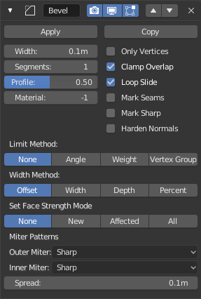
The Bevel modifier.
- Ширина – Width
The size of the bevel effect. See Width Method below.
- Сегменти – Segments
- Кількість петель ребер, доданих уздовж грані скосу.
- Профіль – Profile
- Форма скосу від угнутої до вигнутої. Він немає жодного впливу, якщо Segments мають значення, менше за 2.
- Матеріал – Material
- Індекс гнізда матеріалу, що використовується для скосу. Коли задано -1, то буде використано матеріал, найближчої оригінальної грані.
- Лише Вершини – Only Vertices
When enabled, only the areas near vertices are beveled, the edges remain unchanged.
- Затиск Перекриття – Clamp Overlap
- Limits the width of each beveled edge so that edges cannot cause overlapping intersections with other geometry.
- Ковзання Петлі – Loop Slide
- Якщо є нескошені ребра уздовж скошених ребер на вершині, то скіс намагатиметься ковзати уздовж цих ребер, при можливості. Вимикання цієї опції може призвести до більш рівномірної ширини скосу.
- Mark Seams
- If a seam edge crosses a non-seam one and you bevel all of them, this option will maintain the expected propagation of seams.
- Mark Sharp
- Similar to Mark Seams, but for sharp edges.
- Harden Normals
- When enabled, the per-vertex face normals of the bevel faces are adjusted to match the surrounding faces, and the normals of the surrounding faces are not affected. This will keep the surrounding faces flat (if they were before), with the bevel faces shading smoothly into them. For this effect to work, you need custom normals data, which requires Auto Smooth option to be enabled (see Normals).
- Метод Ліміту – Limit Method
Використовується для керування тим, де скіс застосовується до сіті.
- Нема – None
- Без ліміту, усі ребра будуть скошені.
- Кут – Angle
- Тільки ребра, де суміжні грані формують кут, менший за визначений, будуть скошені. Призначено, щоб дозволити вам скошувати тільки гострі ребра об’єкта без впливу на його згладжені поверхні.
- Вагомість – Weight
- Використовує вагомість скосу кожного ребра для визначення ширини скосу. Коли ця вагомість скосу є 0.0, то скіс не застосовується. Дивіться про коригування вагомостей скосу тут – here.
- Група Вершин – Vertex Group
- Використовує вагомості з групи вершин для визначення ширини скосу. Коли вагомість вершини є 0.0, то скіс не застосовується. Ребро буде скошене тільки тоді, коли обидві його вершини входять у вказану групу вершин. Дивіться про коригування вагомостей груп вершин тут – here.
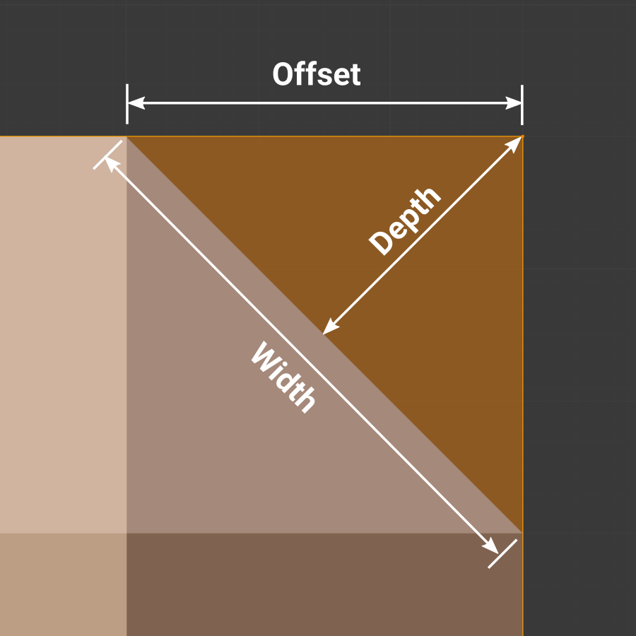
- Метод Ширини – Width Method
Визначає те, як тлумачиться Ширина для визначення величини скосу.
- Зсув – Offset
- Значення тлумачиться як відстань від оригінального ребра до ребра скошеної грані.
- Ширина – Width
- Значення інтерпретується як відстань між двома новими ребрами, формованими скосом.
- Глибина – Depth
- Значення - відстань перпендикуляра від нової скошеної грані до оригінального ребра.
- Відсоток – Percent
- Подібно до Offset, але значення тлумачиться як відсоток довжини суміжного ребра.
- Set Face Strength Mode
Set Face Strength on the faces involved in the bevel, according to the mode specified here. This can be used in conjunction with a following Weighted Normals modifier (with the Face Influence option checked).
- Нема – None
- Do not set face strength.
- New
- Set the face strength of new faces along edges to Medium, and the face strength of new faces at vertices to Weak.
- Affected
- In addition to those set for the New case, also set the faces adjacent to new faces to have strength Strong.
- All
- In addition to those set for the Affected case, also set all the rest of the faces of the model to have strength Strong.
- Miter Patterns
A miter is formed when two beveled edges meet at an angle. On the side where the angle is greater than 180 degrees, if any, it is called an outer miter. If it is less than 180 degrees, then it is called an inner miter. The outer and inner miters can each be set to one of these patterns:
- Sharp
- Edges meet at a sharp point, with no extra vertices introduced on the edges.
- Patch
Edges meet at a sharp point but in addition, two extra vertices are introduced near the point so that the edges and faces at the vertex may be less pinched together than what occurs in the Sharp case. This pattern does makes no sense for inner miters, so it behaves like Arc for them.
The Spread slider controls how far the new vertices are from the meeting point.
- Arc
Two vertices are introduced near the meeting point, and a curved arc joins them together.
The Spread slider controls how far the new vertices are from the meeting point.
The Profile slider controls the shape of the arc.
Diagrams of the miter patterns.¶ 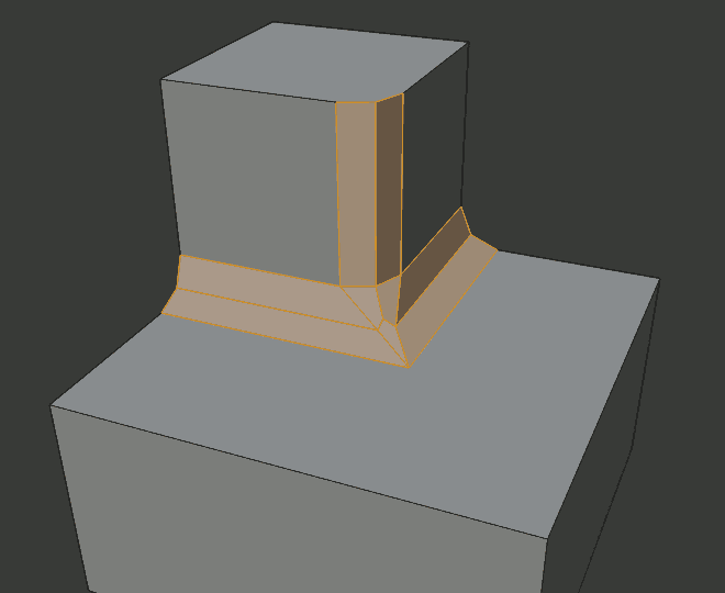
Sharp outer miter.
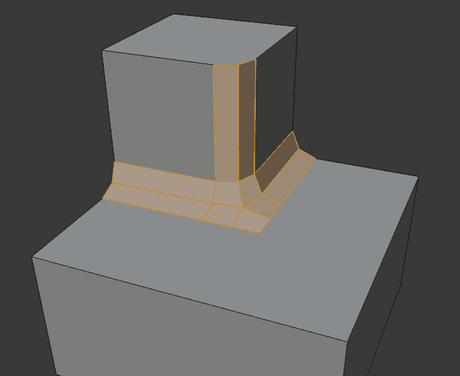
Patch outer miter.
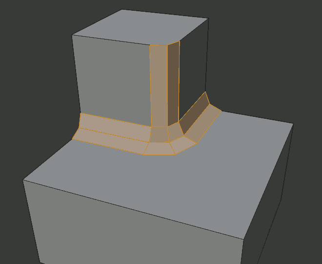
Arc outer miter.
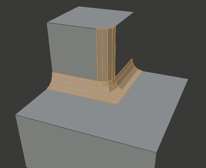
Sharp inner miter.
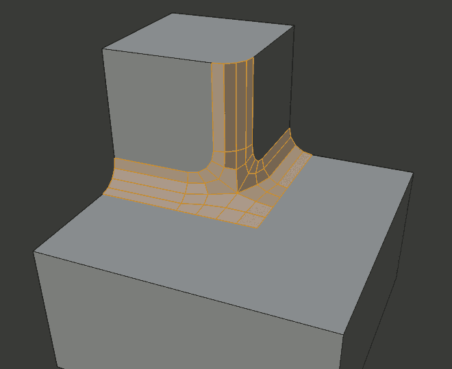
Arc inner miter.
- Spread
- The value used to spread extra vertices apart for non-sharp miters.
