Інструменти Ребер – Edge Tools
Орієнтир – Reference
| Mode: | Edit Mode |
|---|---|
| Menu: | |
| Hotkey: | Ctrl-E |
New Edge/Face from Vertices
Орієнтир – Reference
| Mode: | Edit Mode |
|---|---|
| Menu: | |
| Hotkey: | F |
Це створить ребро або деякі грані, залежно від вашого виділення.
Дивіться також тут – Creating Geometry.
Установлення атрибутів ребер
Ребра можуть мати кілька різних атрибутів, що впливають на те, як певні інші інструменти впливають на сіть.
Позначити Шов – Mark Seam та Зчистити Шов – Clear Seam
Орієнтир – Reference
| Mode: | Edit Mode |
|---|---|
| Menu: |
Seams are a way to create separations, «islands», in UV maps. See the UV Mapping section for more details. These operators set or unset this flag for selected edges.
Позначити Гостроту – Mark Sharp та Зчистити Гостроту – Clear Sharp
Орієнтир – Reference
| Mode: | Edit Mode |
|---|---|
| Menu: |
The Sharp flag is used by the split normals and the Edge Split modifier, which are part of the smoothing/customized shading techniques. As seams, it is a property of edges, and these operators set or unset it for selected ones.
Коригування вагомості скосу
Орієнтир – Reference
| Mode: | Edit Mode |
|---|---|
| Menu: |
This edge property, a value between (0.0 to 1.0), is used by the Bevel Modifier to control the bevel intensity of the edges. This operator enters an interactive mode (a bit like transform tools), where by moving the mouse (or typing a value with the keyboard) you can set the bevel weight of selected edges. If two or more edges are selected, this operator alters the average weight of the edges.
Дивись також
Vertices also have a bevel weight which can be edited.
Складка на Ребрі – Edge Crease
Орієнтир – Reference
| Mode: | Edit Mode |
|---|---|
| Menu: | |
| Hotkey: | Shift-E |
This edge property, a value between (0.0 to 1.0), is used by the Subdivision Surface Modifier to control the sharpness of the edges in the subdivided mesh. This operator enters an interactive mode (a bit like transform tools), where by moving the mouse (or typing a value with the keyboard) you can set the (average) crease value of selected edges. A negative value will subtract from the actual crease value, if present. To clear the crease edge property, enter a value of -1.
Ковзання Ребра – Edge Slide
Орієнтир – Reference
| Mode: | Edit Mode |
|---|---|
| Menu: |
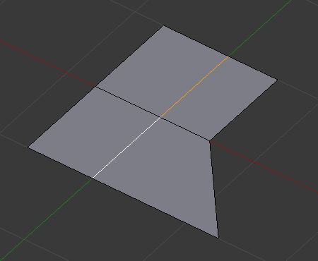
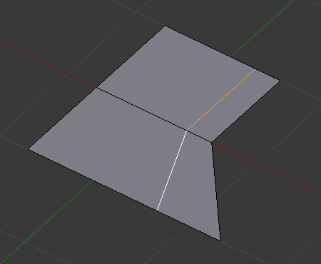
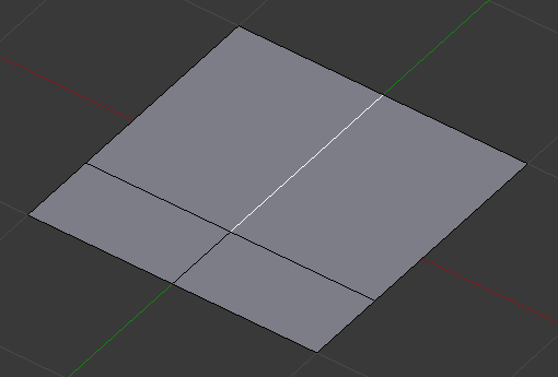
Ковзання одного або більше ребер по суміжних гранях з деякими обмеженнями задіює виділення ребер (тобто, таке виділення повинно визначати дійсну петлю, дивіться нижче).
- Рівно – Even E
- Змушує петлю ребер відповідати формі сусідньої петлі ребер. Ви можете перевернути на протилежну вершину, використовуючи F. Використовуйте Alt-Wheel для зміни керування ребрами.
- Flipped F
- При активному режимі Even це перевертає між двома суміжними петлями ребер активну петлю ребер, яка повинна з ними узгоджуватися.
- Затиск – Clamp Alt або C
- Перемикає затискання ковзання у межах розширу ребер.
- Фактор – Factor
- Визначає величину здійсненого ковзання. Від’ємні значення відповідають ковзанням у напрямку однієї грані, тоді як додатні – у напрямку іншої. Це також показується у заголовку 3D Огляду.
- Дзеркальне Редагування – Mirror Editing
- Дозволяє вам поширювати цю операцію на симетричні елементи сіті (якщо такі присутні, у локальному напрямку X).
- Коригування UV – Correct UVs
- Коригує відповідні координати UV, якщо такі існують, для запобігання спотворенням зображення.
Використання
Стандартно, позиція вершин на петлі ребер рухається як відсоток від відстані між їх оригінальною позицією та суміжною петлею ребер, незалежно від довжини ребер.
Режим «Рівн
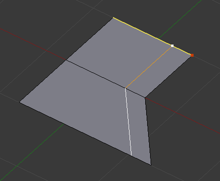
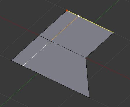
Режим Even утримує форму виділеної петлі ребер такою ж, як у суміжної з неї петлі ребер, а не ковзає з відсотком уздовж кожного перпендикулярного ребра.
In Even mode, the tool shows the position along the length of the currently selected edge which is marked in yellow, from the vertex that has an enlarged red marker. Movement of the sliding edge loop is restricted to this length. As you move the mouse the length indicator in the header changes showing where along the length of the edge you are.
Для зміни керувального ребра, що визначає позицію петлі ребер, використовуйте Alt-Wheel для прокрутки до іншого ребра.
Рухання миші пересуває виділену петлю ребер у напрямку до або від стартової вершини, але лінія петлі буде рухатися тільки у межах довжини поточно обраного ребра, відповідаючи формі однієї з межових петель ребер.
Обмеження та обходи
Існують обмеження щодо типу виділення ребер для цієї операції. Хибними виділеннями є:
- Петля, що перетинає себе
- This means that the tool could not find any suitable faces that were adjacent to the selected edge(s). An example that shows this is selecting two edges that share the same face. A face cannot be adjacent to itself.
- Одночасно кілька петель ребер
- The selected edges are not in the same edge loop, which means they do not have a common edge. You can minimize this error by always selecting edges end-to-end or in a «chain». If you select multiple edges just make sure they are connected. This will decrease the possibility of getting looping errors.
- Border Edges
- Виділення одиничного ребра на одному з країв об’єкта. Петля ребер не може бути знайдена, оскільки тут є тільки одна грань. Пам’ятайте, що петлі ребер є петлями, що є відтинками двох або більше граней.
A general rule of thumb is that if multiple edges are selected they should be connected end-to-end such that they form a continuous chain. This is literally a general rule because you can still select edges in a chain that are invalid because some of the edges in the chain are in different edge loops.
Обернути Ребро – Rotate Edge
Орієнтир – Reference
| Mode: | Edit Mode |
|---|---|
| Menu: |
Rotating an edge clockwise (CW) or counter-clockwise (CCW) spins an edge between two faces around their vertices. This is very useful for restructuring a mesh’s topology.
Цей інструмент працює на виділених ребрах або спільному ребрі між виділеними гранями.
Попередження
To rotate an edge based on faces you must select adjacent face pairs, otherwise Blender notifies you with an error message, «Could not find any select edges that can be rotated». Using either Rotate Edge CW or Rotate Edge CCW will produce exactly the same results as if you had selected the common edge.
Розділ Ребром – Edge Split
Орієнтир – Reference
| Mode: | Edit Mode |
|---|---|
| Menu: |
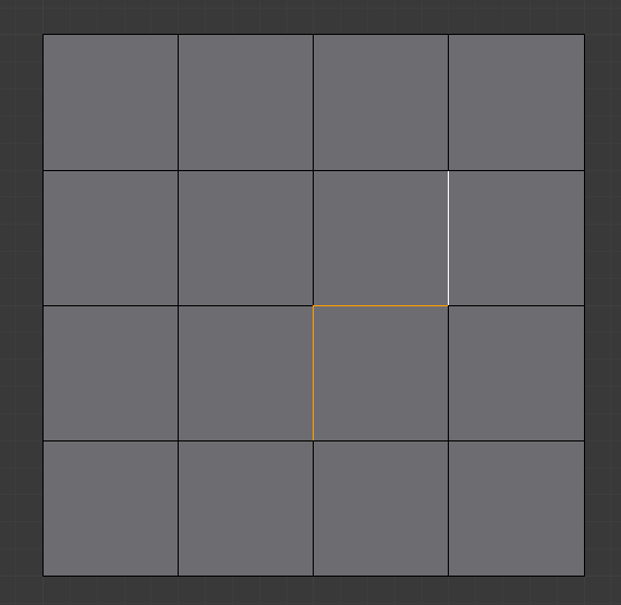
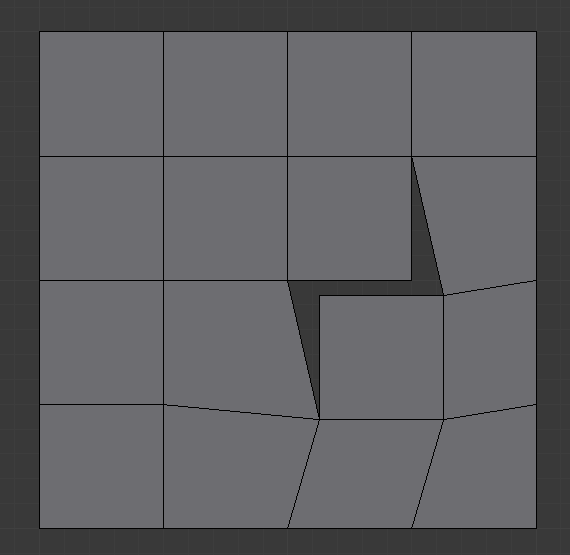
Edge Split is similar to the Rip tool. When two or more touching interior edges, or a border edge is selected when using Edge Split, a hole will be created, and the selected edges will be duplicated to form the border of the hole.
Мостити Петлі Ребер – Bridge Edge Loops
Орієнтир – Reference
| Mode: | Edit Mode |
|---|---|
| Menu: |
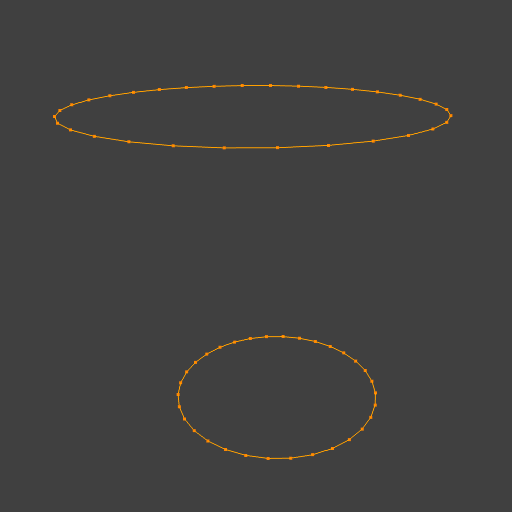
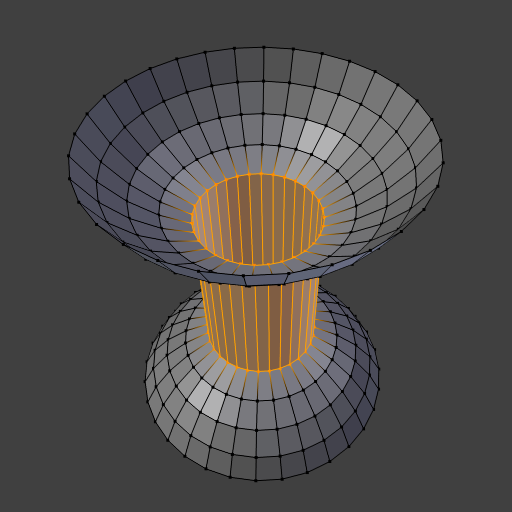
Bridge Edge Loops з’єднують одночасно кілька петель ребер гранями між ними.
- З’єднання Петель – Connect Loops
- Відкрита Петля – Open Loop
- Петлі з’єднуються з відкритими кінцями.
- Закрита Петля – Closed Loop
- Tries to connect to a circular loop (where start and end are merged).
- Пари Петель – Loop pairs
- З’єднує кожну пару однаковою кількістю петель окремо.
- Об’єднання – Merge
- Об’єднує петлі ребер, а не створює нову грань.
- Фактор Об’єднання – Merge Factor
- Which edge loop the edges are merged to, a value of 0.5 will merge at a half-way point.
- Закрут – Twist
- Визначає, які вершини в обох петлях з’єднуються одна з одною.
- Кількість Поділів – Number of Cuts
- Кількість проміжних петель ребер, використовуваних для мостіння відстані між двома петлями.
- Інтерполяція – Interpolation
- Лінеарно – Linear, Шлях Змішання – Blend Path, Поверхня Змішання – Blend Surface
- Згладженість – Smoothness
- Згладженість для Blend Path та Blend Surface.
- Фактор Профілю – Profile Factor
- Наскільки проміжні нові ребра звужено/розширено.
- Форма Профілю – Profile Shape
- The shape of the new edges. See the Proportional Editing page for a description of each option.
Приклади
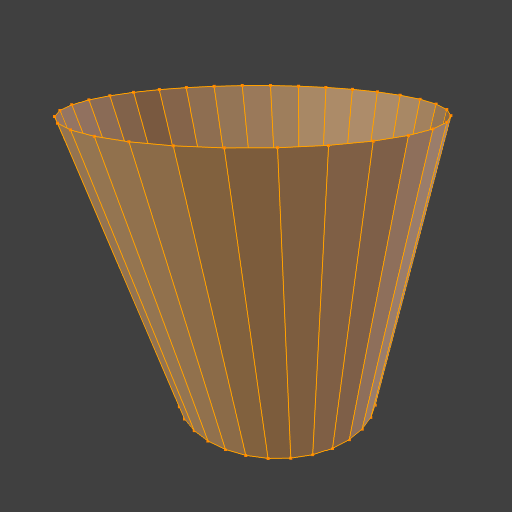
Простий приклад, що показує дві закриті петлі ребер.
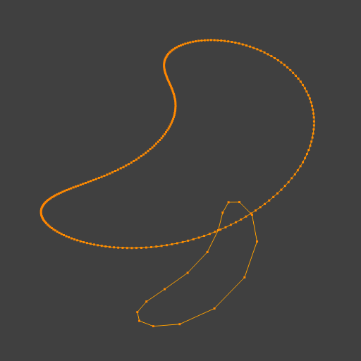
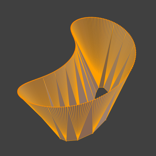
Приклад засобу Bridge між петлями ребер з різними кількостями вершин.
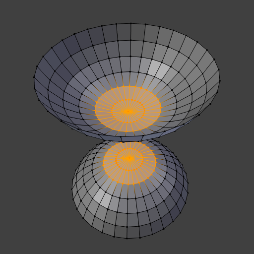
Приклад використання інструмента Bridge для вирізання отворів у виділеннях граней та з’єднання їх.
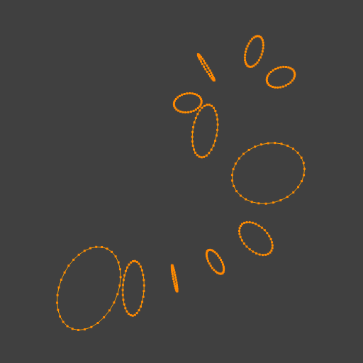
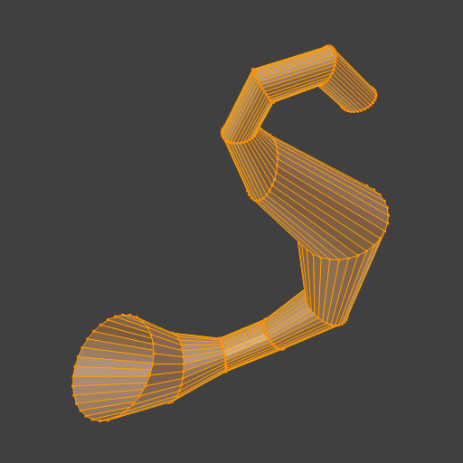
Приклад, що показує як засіб Bridge може виявляти одночасно кілька петель та з’єднувати їх за один крок.
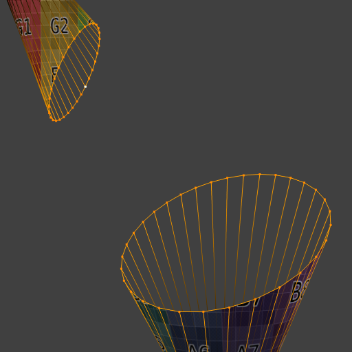
Приклад опції підподілення та змішування поверхні з UV.
