Transform Orientation
Reference
- Mode:
Object and Edit Modes
- Panel:
- Shortcut:
Comma
The Transform Orientation determines the orientation of the Object Gizmo. Changing this orientation can make it easier to perform transformations in the direction you want.
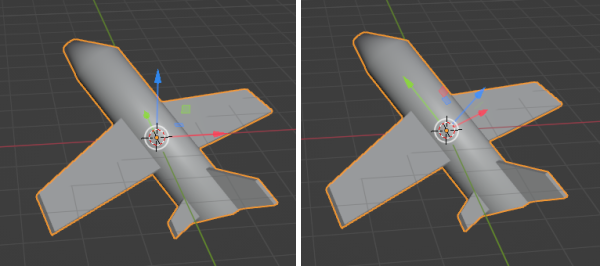
With the default Global transform orientation (left) it’s tricky to move the plane in the direction it’s facing, but with Local (right) it’s easy.
The Transform Orientation can be changed using a selector in the 3D Viewport’s header:

Transform Orientation selector.
The orientation can also be changed temporarily while performing a hotkey-based transformation with axis locking. For example, if you first press G to start moving an object, then X to lock to the orientation’s X axis, and finally X a second time, you’ll get a lock to an alternative orientation: the Local orientation if it was Global previously, and the Global orientation otherwise.
In addition to the builtin orientations, you can also define your own (see Custom Orientations below).
Orientations
- Global
Align the transformation axes to world space. The world axes are shown by the Navigation Gizmo in the top right corner of the viewport, as well as the Grid Floor.
- Local
Align the transformation axes to the active object’s orientation.
- Normal
In Edit Mode, orient the transformation axes so that the Z axis of the gizmo matches the average Normal of the selected elements.
In Object Mode, this is equivalent to Local orientation.
- Gimbal
Orient the transformation axes to visualize the workings of the object’s Rotation Mode. This is specifically useful for the Euler modes, where the object is rotated one axis at a time: the rotation axes don’t stay perpendicular to each other and might even overlap, a phenomenon known as gimbal lock that complicates animation.
- View
Align the transformation axes to the view (meaning they change as you orbit around):
X: Left/Right
Y: Up/Down
Z: Towards/Away from the screen
- Cursor
Align the transformation axes to the 3D Cursor.
- Parent
Align the transformation axes to the Parent.
Examples
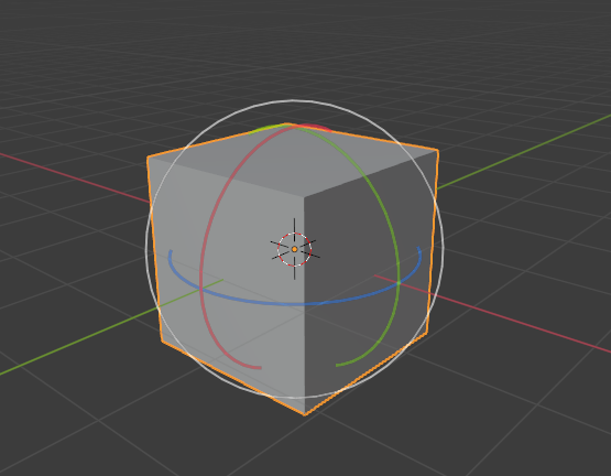
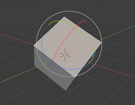
Default cube with Global transform orientation selected.¶ |
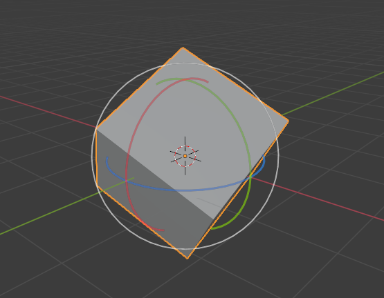
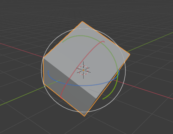
Rotated cube with Global orientation, gizmo has not changed.¶ |
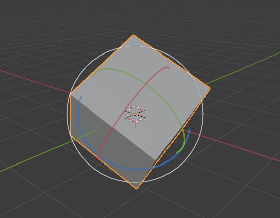
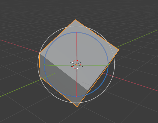
Local orientation, gizmo matches the object’s rotation.¶ |
Normal orientation, in Edit Mode.¶ |
Gimbal transform orientation.¶ |
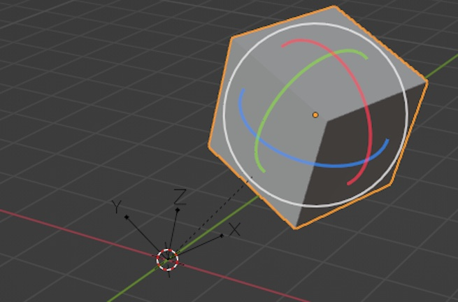
View transform orientation.¶ |
Parent transform orientation. Cube parented to rotated empty.¶ |
Custom Orientations
Reference
- Mode:
Object and Edit Modes
- Panel:
You can define custom transform orientations using objects or mesh elements. Custom orientations defined from an object use the Local orientation of that object, whereas those defined from mesh elements (vertices, edges, faces) use the average Normal orientation of those elements.
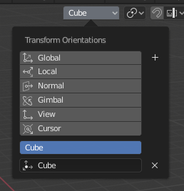
Transform Orientation panel.
The Transform Orientation panel, found in the header of the 3D Viewport, can be used to select, add, remove, and rename transform orientations.
The default name for these orientations is derived from the selection. If it’s an object it will take that object’s name, if it’s an edge it will be titled «Edge», and so on.
Create Orientation
To create a custom orientation, select an object or mesh element(s) and click the «+» button in the Transform Orientation panel.
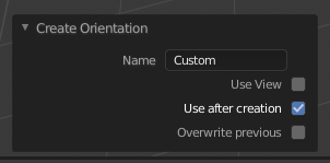
Create Orientation Adjust Last Operation panel.
Right after creating the orientation, the Create Orientation Adjust Last Operation panel gives a few options:
- Name
Text field for naming the new orientation.
- Use View
The new orientation will be aligned to the view space.
- Use After Creation
The new orientation stays selected.
- Overwrite Previous
If the new orientation is given an existing name, a suffix will be added to its name to avoid overwriting the existing orientation, unless Overwrite Previous is checked, in which case it will be overwritten.
Delete Orientation
To delete a custom orientation, simply select it and click the × button.