Noise Texture Node
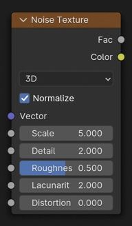
The Noise Texture node evaluates a fractal Perlin noise at the input texture coordinates. It can be used for a single Perlin noise evaluation, or for combining multiple octaves (layers) with increasingly finer detail.
Inputs
The inputs are dynamic: they become available if needed depending on the node properties.
- Vector
Texture coordinate to evaluate the noise at; defaults to Generated texture coordinates if the socket is left unconnected.
- W
Texture coordinate to evaluate the noise at.
- Scale
Scale of the base noise octave.
- Detail
Number of noise octaves. This can have a fractional part, in which case a blend is performed (e.g. a Detail of 2.5 results in a 50% blend between 2 and 3 octaves).
- Roughness
Blend between a smoother noise pattern, and rougher with sharper peaks.
- Lacunarity
The difference between the scale of each two consecutive octaves. Larger values corresponds to larger scale for higher octaves.
- Offset
An added offset to each octave, determines the level where the highest octave will appear.
- Gain
An extra multiplier to tune the magnitude of octaves.
- Distortion
Amount of distortion.
Properties
- Dimensions
The dimensions of the space to evaluate the noise in.
- 1D:
Evaluate the noise in 1D space at the input W.
- 2D:
Evaluate the noise in 2D space at the input Vector. The Z component is ignored.
- 3D:
Evaluate the noise in 3D space at the input Vector.
- 4D:
Evaluate the noise in 4D space at the input Vector and the input W as the fourth dimension.
Merknad
Higher dimensions corresponds to higher render time, so lower dimensions should be used unless higher dimensions are necessary.
- Type
Type of Noise texture, with different ways to combine octaves.
- fBM:
Fractal Brownian motion, produces a homogeneous and isotropic result. Values from octaves are added together.
- Multifractal:
More uneven, varying by location similar to real terrain. Values from octaves are multiplied together.
- Hybrid Multifractal:
Creates peaks and valleys with different roughness values, like real mountains rise out of flat plains. Combines octaves using both addition and multiplication.
- Ridged Multifractal:
Creates sharp peaks. Calculates the absolute value of the noise, creating «canyons», and then flips the surface upside down.
- Hetero Terrain:
Similar to Hybrid Multifractal creates a heterogeneous terrain, but with the likeness of river channels.
- Normalize fBM
If enabled, ensures that the output values stay in the range 0.0 to 1.0. If disabled, the range is at most -(Detail + 1) to Detail + 1 (smaller if Roughness < 1).
Outputs
- Factor
Value of fractal noise.
- Color
Color with different fractal noise in each component.
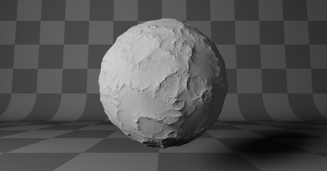
Examples
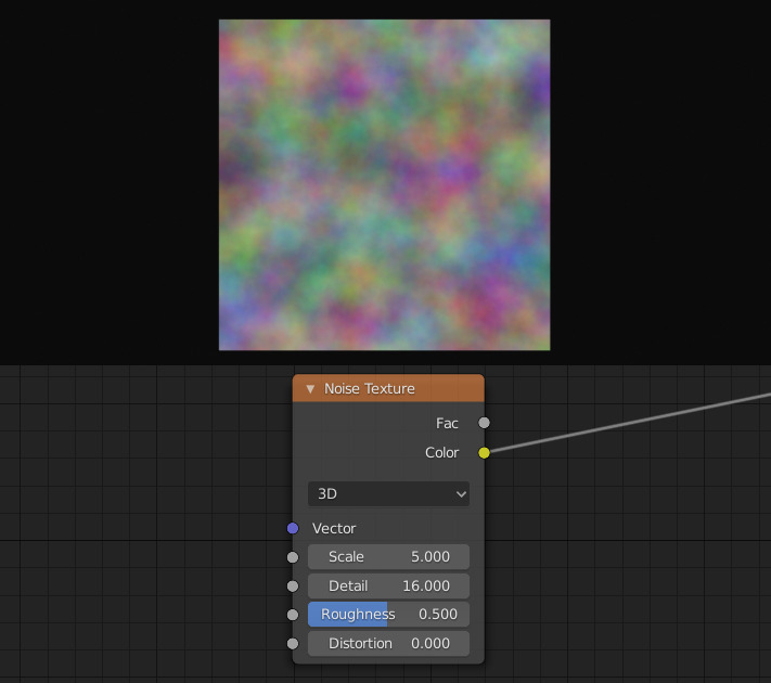
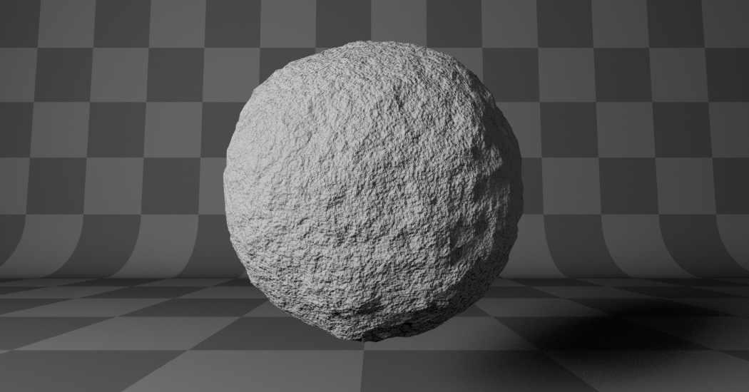
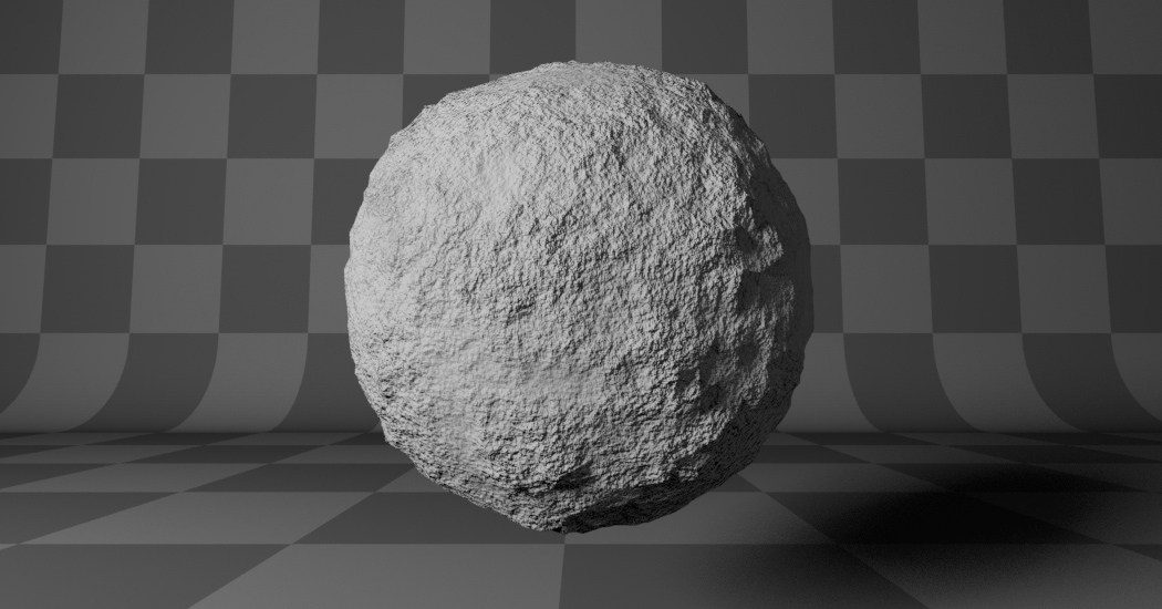
Noise Texture with high detail.


Notes
While the noise is random in nature, it follows a certain pattern that might not evaluate to random values in some configurations. For instance, consider the following configuration where a grid of objects have a material that evaluates a noise texture at their locations. One might expect the objects to have random values since they have different locations, but this is not the case.
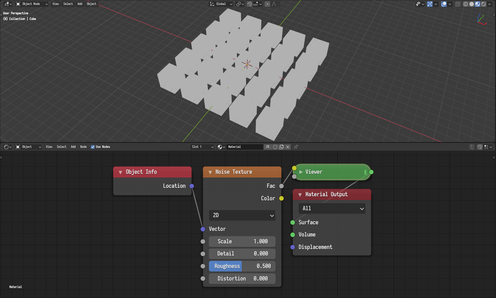
An example configuration where the noise evaluates to a constant value.
It seems all objects have a value of 0.5. To understand why this happens, let us look at the following plot of a 1D noise texture.
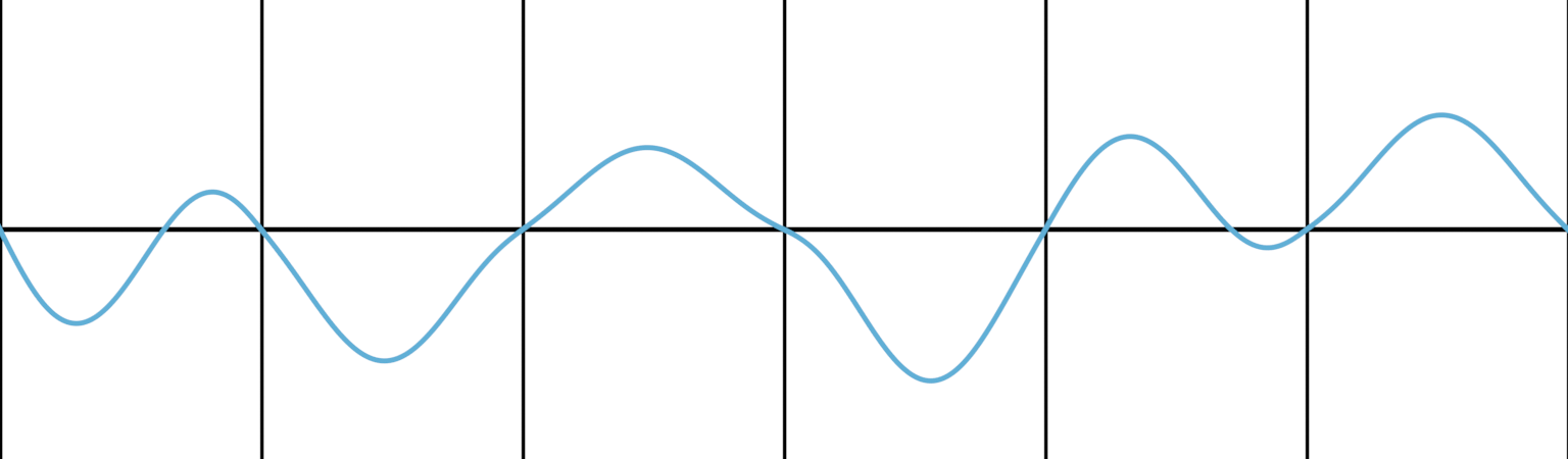
A plot of a 1D noise with zero details and zero distortion.
The horizontal line denotes a value of 0.5 and the vertical lines denotes whole numbers assuming a noise scale of 1. As can be seen, the noise always intersects the 0.5 line at whole numbers. Since the aforementioned objects were distributed on a grid and have whole number locations, they all evaluate to 0.5. Which explains the issue at hand.
Generally, any discrete evaluation of noise at integer multiples of the reciprocal of the noise scale will always evaluate to 0.5. It also follows that evaluations closer to that will have values close to 0.5. In such cases, it is almost always preferred to use the White Noise Texture.
Regardless, one can mitigate this issue in a number of ways:
Adjust the scale of the noise to avoid aligning the noise with the evaluation domain.
Add an arbitrary offset to the texture coordinates to break the alignment with the evaluation domain.
Evaluate the noise at a higher dimension and adjust the extra dimension until a satisfactory result is achieved.
|
Constant value issue.¶ |
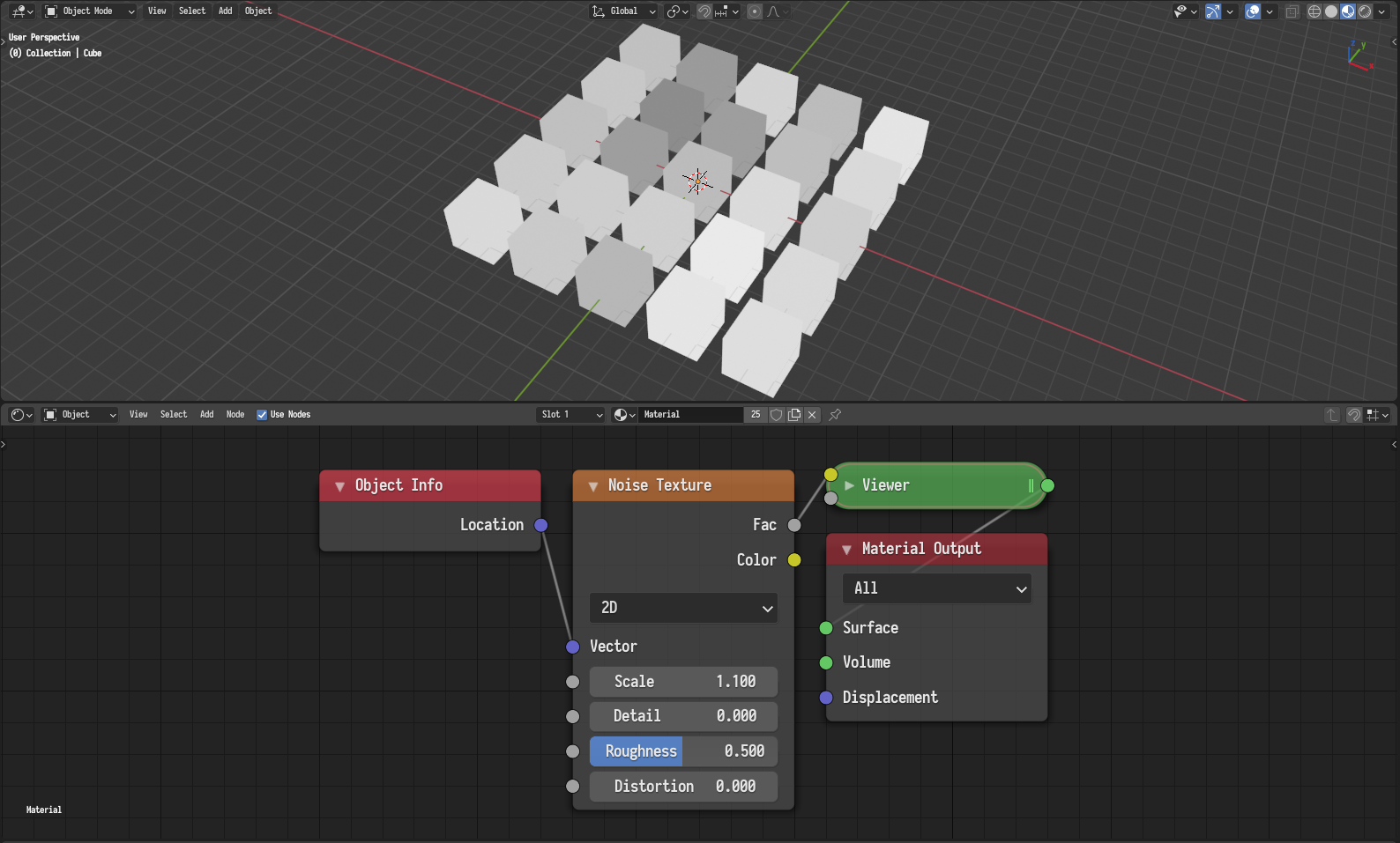
Mitigating the issue by adjusting the scale.¶ |
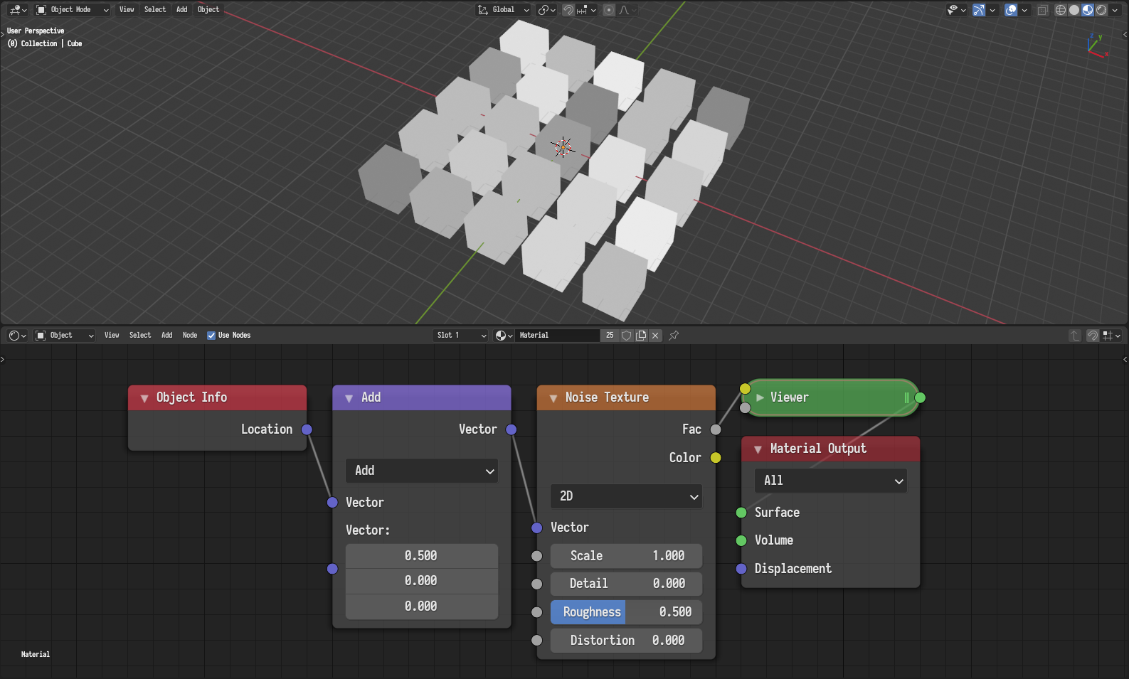
Mitigating the issue by adding an arbitrary offset.¶ |
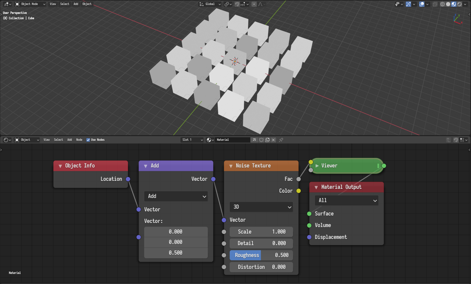
Mitigating the issue by evaluating at a higher dimension.¶ |
Similarly, in other configurations, one might experience some banding patterns in the noise, where there are bands of high contrast areas followed by banding of low contrast areas. For instance, planar surfaces that are slightly tilted along one of the axis will have such a banding pattern.
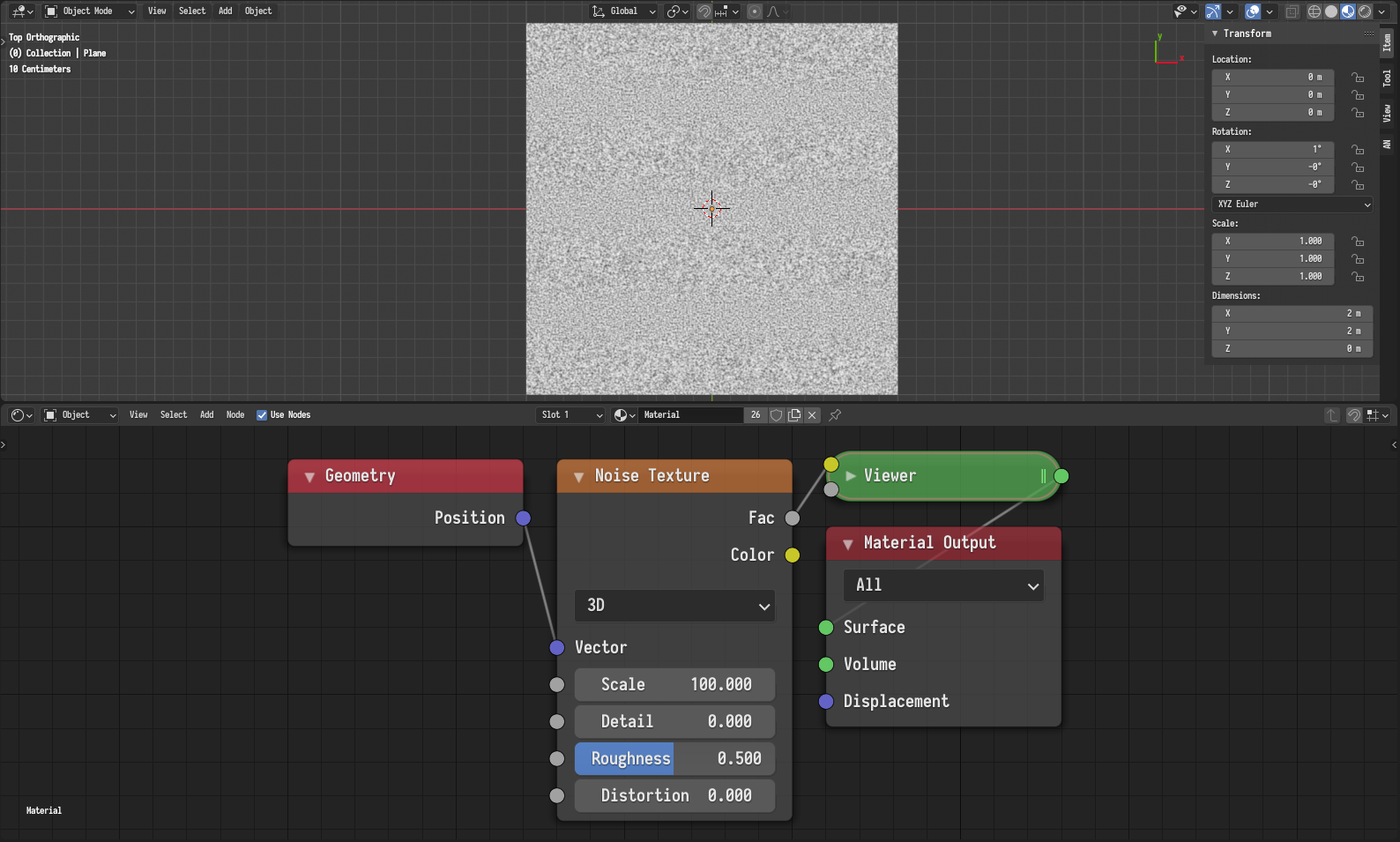
An example configuration where the noise have a banding pattern.
This happens because the slight tilt along one of the axis causes values along the perpendicular axis to change very slowly making the grid structure of the noise more apparent. The easiest way to mitigate this issue to rotate the coordinates by an arbitrary amount.
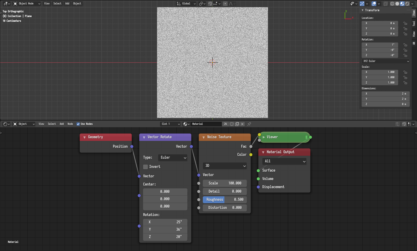
Mitigating the issue by rotating the coordinates by an arbitrary amount.