Viewport Display
Reference
- Mode:
All Modes
- Panel:

The Display panel.
- Display As
This controls the way all the bones of the armature appear in the 3D Viewport. Individual bones can also override this using bone Display Type.
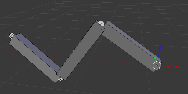
- Octahedral
This is the default visualization, well suited for most of editing tasks. It materializes:
The bone root (”big” joint) and tip (”small” joint).
The bone ”size” (its thickness is proportional to its length).
The bone roll (as it has a square section).
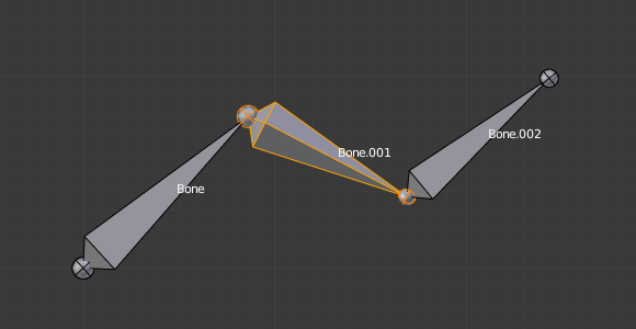
Note the 40° rolled Bone.001 bone.
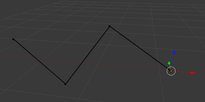
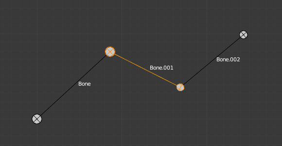
- Stick
This is the simplest and most non-intrusive visualization. It just materializes bones by sticks of constant (and small) thickness, so it gives you no information about root and tip, nor bone size or roll angle.
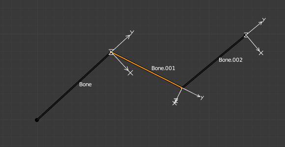
Note that Bone.001 roll angle is not visible (except by its XZ axes).
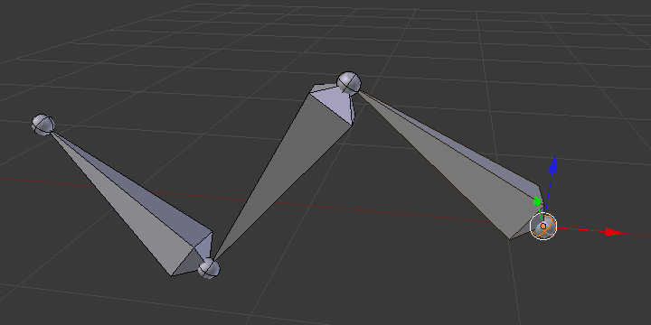
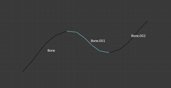
- B-Bone
This visualization shows the curves of ”smooth” multi-segmented bones; see the Bendy Bones for details.
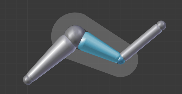
- Envelope
This visualization materializes the bone deformation influence. More on this in the bone page.
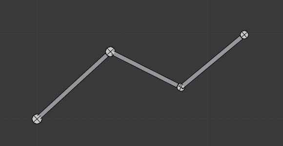
- Wire
This simplest visualization shows the curves of ”smooth” multi-segmented bones.


- Show
- Names
Displays the name of each bone.
- Shapes
When enabled, the default standard bone shape is replaced, in Object Mode and Pose Mode, by the shape of a chosen object (see Shaped Bones for details).
- Bone Colors
Draws bones in their configured colors. Disable to always draw bones in the default color. For more details see Bone Colors.
- In Front
When enabled, the bones of the armature will always be shown on top of the solid objects (meshes, surfaces, …). I.e. they will always be visible and selectable (this is the same option as the one found in the Display panel of the Object data tab). Very useful when not in Wireframe mode.
- Axis
When enabled, the (local) axes of each bone are displayed (only relevant for Edit Mode and Pose Mode).
- Position
The position for the axes display on the bone. Increasing the value moves it closer to the tip; decreasing moves it closer to the root.
- Relations
Whether the Relationship Lines overlay should be drawn from each parent’s tail or head. The lines are always drawn towards the children’s heads.