Map UV Node
Map a texture using UV coordinates, to apply a texture to objects in compositing.
May be used in combination with Cryptomatte Node to apply the texture only to specific objects.
Inputs
- Image
The new 2D texture.
- UV
The input for UV render pass. See Cycles render passes.
Vihje
To store the UV pass a multi-layer OpenEXR format could be used.
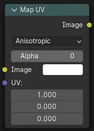
Properties
- Filter Type
Interpolation Methods.
- Anisotropic:
Enhances the clarity of textures viewed at oblique angles, addressing issues like blurring and distortion.
- Nearest:
No interpolation, uses nearest neighboring pixel.
- Alpha
Alpha threshold is used to fade out pixels on boundaries.
Outputs
- Image
The resulting image is the input image texture distorted to match the UV coordinates. That image can then be overlay mixed with the original image to paint the texture on top of the original. Adjust alpha and the mix factor to control how much the new texture overlays the old.
Vihje
When painting the new texture, it helps to have the UV maps for the original objects in the scene, it is recommended to keep those UV texture outlines around even, when shooting is done.
Examples
In the example below, we have overlaid a grid pattern on top of the two heads after they have been rendered. During rendering, we enabled the UV layer in the Properties . Using a Mix node (”Overlay” in figure), we mix that new UV texture over the original face. We can use this grid texture to help in any motion tracking that we need to do.
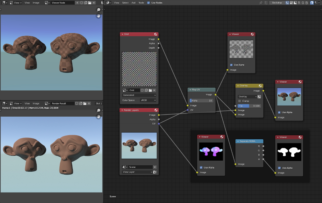
Adding a grid UV textures for motion tracking.
In the next example, we overlay a logo on top of a mesh composed of two intersecting cubes, and we ensure that we Enable the Alpha premultiply button on the Mix node. The logo is used as additional UV texture on top of the existing texture. Other examples include the possibility that there was used an unauthorized product box during the initial animation, and it is needed to substitute in a different product sponsor after rendering.
Vihje
Due to limits of this node, it is not recommended to rush pre-production rendering under the guise of ”fixing it later”.
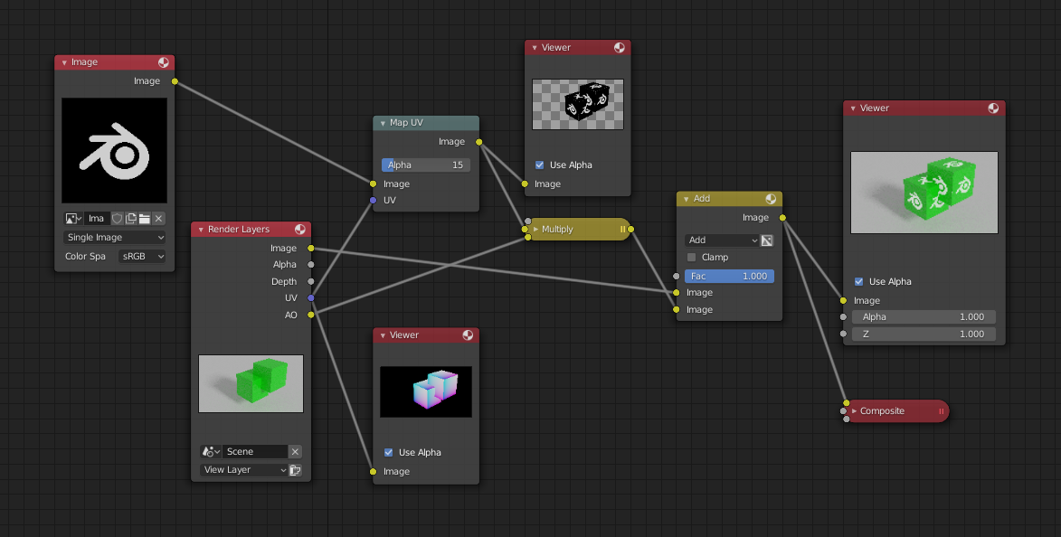
Adding UV textures in post-production.