Node Parts
All nodes in Blender are based on a similar construction. This applies to any type of node. These parts include the title, sockets, properties and more.
Title
The title shows the name/type of the node; it can be overridden by changing the node's Label. On the left side of the title is the collapse toggle which can be used to collapse the node. This can also be done with H.
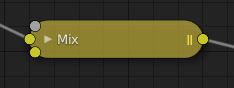
How a node appears when collapsed.
預覽
Previews are an overlay that shows a small image above the node displaying the node result. Not all nodes support previews, but the ones that do can be toggled using the / icons in the top right-hand corner of the node next to the title.
Previews can be disabled for the whole node tree by using Previews overlay toggle.
Sockets
Sockets are input and output values for the node. They appear as little colored circles on either side of the node. Unused sockets can be hidden with Ctrl-H.
Each socket is color-coded depending on what type of data it handles.
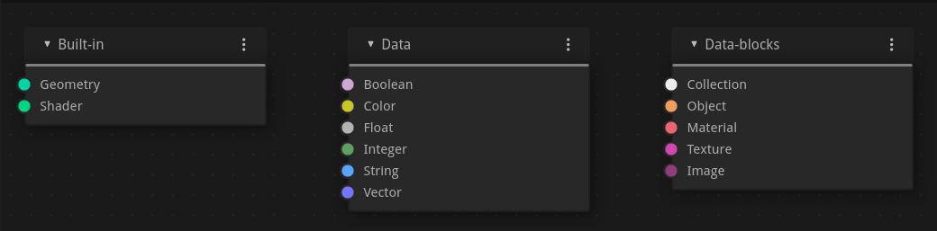
Built-in
- Shader (bright green)
- Geometry (Sea Green)
Used in Geometry Nodes.
- Menu (Dark Gray)
Used for enum style inputs that show a dropdown menu or radio button in the UI.
- Bundle (dark turquoise)
Represents a generic bundle of multiple data types. Bundles can contain several values (e.g., geometry, vectors, or colors) grouped together, allowing compact data transfer between nodes.
- Closure (light brown)
Used in Shader Nodes and Geometry Nodes for logical or procedural encapsulation. A closure can store and pass groups of node inputs and logic, enabling reusable "callable" node behaviors.
Data
- Boolean (light pink)
Used to pass a true or false value.
- Color (yellow)
Indicates that the socket accepts/produces color information. The colors may or may not have an alpha component depending on the node tree type.
- Float (light gray)
Indicates that the socket accepts/produces floating-point numbers.
- Integer (lime green)
Used to pass an integer value (a number without a fractional component).
- Integer Vector (slate blue)
A vector made of integer values which can be either two or three-dimensional.
- String (light blue)
Used to pass a text value.
- Vector (dark blue)
Represents vector data such as coordinates and normals. Vectors can have 2, 3, or 4 components:
2D: Shows and uses only X and Y components.
3D: Includes X, Y, and Z components.
4D: Includes X, Y, Z, and W components.
- Rotation (pink)
Indicates a rotation/quaternion.
- Matrix (dark pink)
Indicates a 4×4 matrix of float values, it is often used to represent a Transformation Matrix.
Data-Blocks
- Collection (white)
Used to pass a collection data-block.
- Object (orange)
Used to pass an object data-block.
- Material (salmon)
Used to pass a material data-block.
- Texture (pink)
Used to pass a texture data-block.
- Image (apricot)
Used to pass an image data-block.
- Font (brown)
Used to pass a font data-block.
Socket Shape
Data sockets can have different shapes, indicating the data structure use to transport data. The data structure determines how values are passed and interpreted. More complex structures allow passing multiple values through a single connection.
- Auto
Automatically detects a good structure type based on how the socket is used.
- Dynamic (Circle)
Socket can work with multiple types of structures.
- Single (Rectangle)
These sockets expects a single value, they are represented by a tall rectangular shape.
- Fields (Diamond)
Represents a value that can vary per element (e.g. per point, edge, or face). You can think of a field as a "value map", similar to how the brightness of pixels in a grayscale image represents varying values across space.
If a single value is connected to a field socket, it is implicitly broadcast all elements receive the same value. It also means that Socket Inspection will show the value instead of field input names.
See also
- Grid (Four Squares)
Represents a grid data structure, which stores values sampled across a 2D surface or a 3D volume. Grids can represent data such as image pixels, voxel densities, or other sampled values in space. They allow complex operations where values are distributed continuously across space, rather than being attached to individual geometry elements.
- Lists (Three Lines)
Represents an ordered collection of values.
Lists can contain any number of items of the same data type and allow multiple values to be passed through a single socket. They are commonly used for operations that gather, filter, sort, or process collections of values.
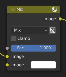
輸入
The inputs are located on the bottom left side of the node, and provide the data the node needs to perform its function. Each input socket, except for the green shader input, when disconnected, has a default value which can be edited via a color, numeric, or vector interface input. In the screenshot of the node above, the second color option is set by a color interface input.
Some nodes have special sockets that can accept multiple inputs. These sockets will have an ellipsis shape rather than a circle to indicate their special behavior.
輸出
The outputs are located on the top right side of the node, and can be connected to the input of nodes further down the node tree.
Conversion
Some socket types can be converted to others either implicitly or explicitly. Implicit conversion happens automatically without the need of a conversion node. For example, Float sockets and Color sockets can be linked to each other.
Once a socket conversion is made, data may be lost and cannot be retrieved later down the node tree. Implicit socket conversion can sometimes change the data units as well. When plugging a Value input node into an angle socket, it'll default to use radians regardless of the scene's Units. This happens because the Value node has no unit while the angle input does.
Valid conversions:
Between color and vector -- mapping between color channels and vector components.
Between color and float -- the color data is converted to its grayscale equivalent.
Color/float/vector to Shader -- implicitly converts to color and gives the result of using an Emission node.
Between float and integer -- integers simply become floats, floats are truncated.
Between float and vector -- when a float becomes a vector the value is used for each component. When a vector becomes a float the average of the components is taken.
Between float and boolean -- values greater than 0 are true, true maps to 1, and false maps to 0.
Between rotations and matrices.
Explicit conversion requires the use of dedicated conversion nodes. Examples include:
Some nodes also provide conversion operations directly. For example, the Math Node node includes functions to convert between degrees and radians.
屬性
Many nodes have settings which can affect the way they interact with inputs and outputs. Node settings are located below the outputs and above any inputs.
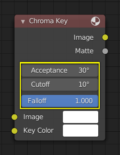
An example of the controls on the Chroma Key node.