Geometry
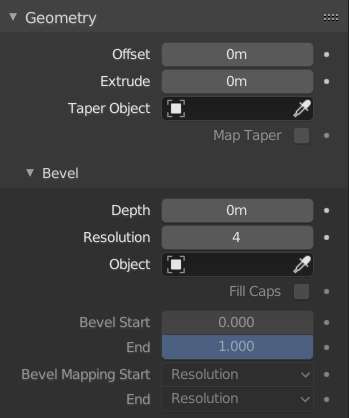
Geometry panel.
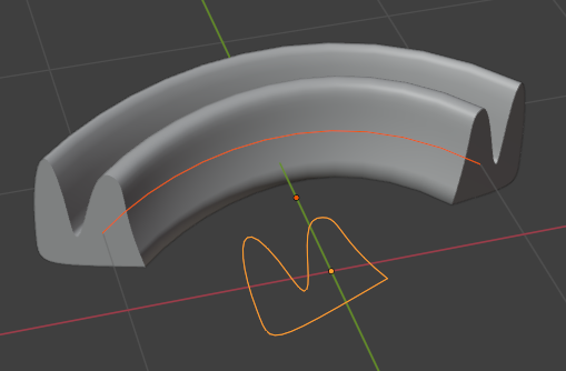
The Geometry panel lets you turn a curve from a 1D line into a 2D ribbon or a 3D tube.
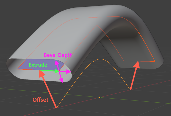
Three copies of the same base curve: one without geometry (bright orange line); one with Offset and Extrude applied (blue ribbon); and one with Offset, Extrude, and Bevel applied (gray tube).
- Offset
Moves the control points along their normals.
- Extrude
Turns the curve from a line into a ribbon by extruding it to the „sides“: at each point, the curve normal is calculated as the „up“ direction, and the curve is extruded to the „left“ and „right.“
Hinweis
You can tweak the direction and distance of Offset and Extrude at each control point by changing its Tilt (rotation around the tangent axis) and Radius (scale factor).
- Taper Object
A separate Curve object, consisting of a single, non-cyclic, 2D spline, that controls the scale factor of the geometry along the length of each of the curve’s splines.
Bemerkung
The „taper“ in the name is misleading: this word means „to reduce in size towards the end,“ while the Taper Object can apply any size anywhere. A better name might have been „Scale Curve.“
Specifically, the Taper Object defines a graph where the X axis represents the position on the curve and the Y axis represents the scale:
The first control point of the Taper Object spline corresponds to the first control point of each geometry spline. Same thing for the last points.
The first Taper point should have the highest X coordinate, and the last point the lowest (try Switch Direction if the scaling doesn’t seem to be working). The specific range of X coordinates doesn’t matter: it could be [-10, 10], [-1, 1], or anything else.
A Y coordinate of 1.0 leaves the geometry unchanged. A coordinate of 0.5 makes it half as large, while 2.0 makes it twice as large.
The Z coordinates of the Taper Object control points are ignored, but if you want, you can set the object’s Shape to „2D“ to force them to 0.
- Taper Radius
How to combine the scale graph of the Taper Object with the radii of the control points.
Bemerkung
As above, this setting is not limited to tapering and does not define any single radius. A better name might have been „Scale Curve Mode.“
- Override:
The Taper Object (scale curve) overrides the radii (scales) of the curve’s control points.
- Multiply:
The scale given by the Taper Object is multiplied by that of the control points.
- Add:
The scale given by the Taper Object is added to that of the control points.
- Map Taper
If geometry is only generated for part of the curve (which can be achieved by changing Factor Start/End), enabling Map Taper will make the endpoints of the Taper Object correspond to those of the geometry instead of those of the curve.
Bevel
Apply a Bevel to turn the 1D line (or 2D ribbon when using Extrude) into a 3D tube.
Round
The cross section of the tube becomes a circle (or pill when using Extrude). You can also get a half circle by changing the Fill Mode.
- Depth
The size of the cross section.
- Resolution
Drives the number of vertices in the cross section.

- Fill Caps
Seals the ends of the tube.
Object
This option lets you fully customize the shape of the cross section by selecting a separate Curve object.
- Object
The curve that defines the cross section. It can be either closed (cyclic) or open.
Wichtig
This curve should be flat in its local XY plane; using another plane will not give the desired result.
Bemerkung
If the selected curve has modifiers, these will not be taken into account. The bevel will use the original curve shape. This happens because curves turn into meshes internally when they have modifiers on them, at which point they can’t be used as cross section curves anymore.
To work around this, you can disable beveling on the path curve, and instead add geometry nodes to it: retrieve the cross section curve using an Object Info Node, convert it from a mesh back into a curve using a Mesh to Curve Node, and finally pass both the path curve and the cross section curve to a Curve to Mesh Node.
Profile
This option lets you customize the shape of the cross section without having to create a separate Curve object. However, unlike the Object option where the curve defines the full cross section, the Profile in the Curve Widget only defines a quarter which is then repeated and mirrored.
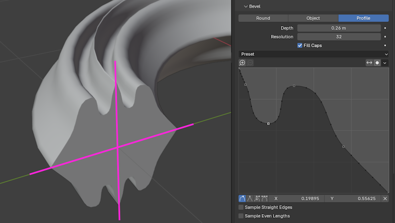
The black dots on the profile represent the points where it’s sampled (that is, where mesh vertices will be created). You can increase the Resolution to get more sample points, and thus a smoother result.
- Preset
You can choose one of the predefined profiles instead of making your own. The Support Loops and Steps presets are generated dynamically based on the Resolution and need to be reapplied if you change it.
- Reverse Path
Mirrors the profile around the diagonal.
- Toggle Profile Clipping
Limits the X and Y coordinates of control points to the range [0, 1].
- Sample Straight Edges
Whether to sample the profile in the middle of perfectly straight segments (lines between two control points with the Vector handle type). This is disabled by default, as it’s normally enough to sample the profile at the control points themselves.
- Sample Even Lengths
By default, each profile segment receives the same number of sample points. By enabling this option, the sample points are instead distributed evenly along the whole length of the profile.
Start & End Mapping
- Factor Start, End
The percentages along the length of the curve where the geometry should start and end. By default, these are set to 0 and 1, making the geometry cover the full length; but if you change them to 0.5 and 0.75, the geometry will only cover the third quarter of the curve.
- Mapping Start, End
How to map the Factor Start, End percentages to positions on the curve.
- Resolution:
Only count control points, disregarding the lengths of the spline segments (pieces of spline between two control points). If a spline has three control points and Factor Start is set to 0.5, the geometry will always start at the second control point, even if its distances to the first and third control points are completely different.
- Segments:
Calculate an approximate percentage along the length of the spline by assuming that all the subdivisions within each segment are evenly distributed.
- Spline:
Calculate an accurate percentage along the length of the spline.
Beispiele
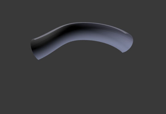
Open 2D Curve
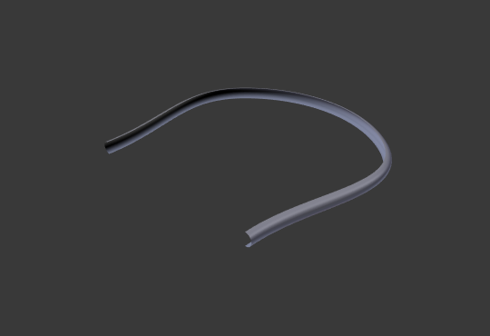
An open (non-cyclic) curve with beveling applied becomes a tube.
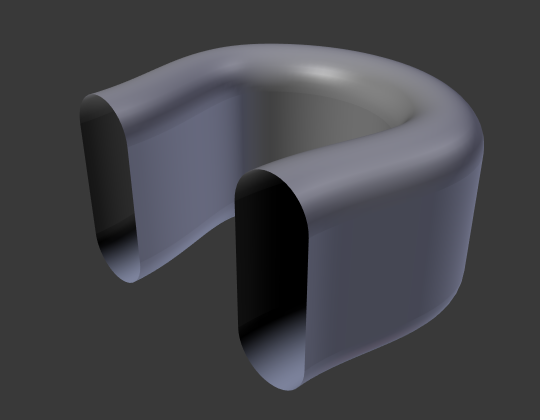
Closed 2D Curve
A closed (cyclic) curve with beveling applied becomes a torus by default. If the curve is 2D and you set the Fill Mode to Both, the top and bottom holes will be filled with flat discs, and you’ll get a cylinder with rounded edges instead.
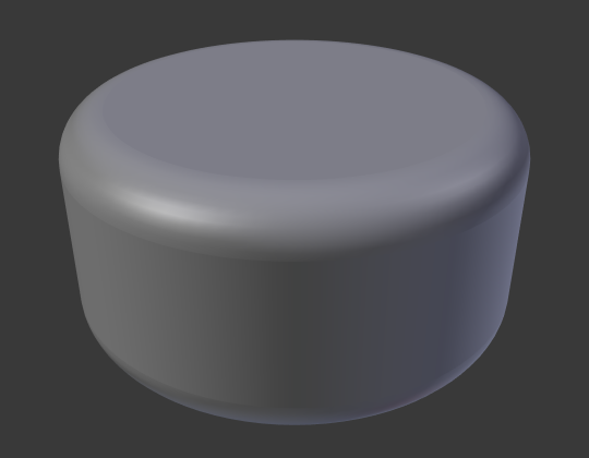
This doesn’t work with 3D curves.
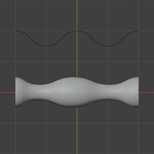
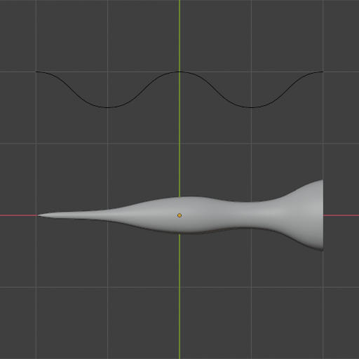
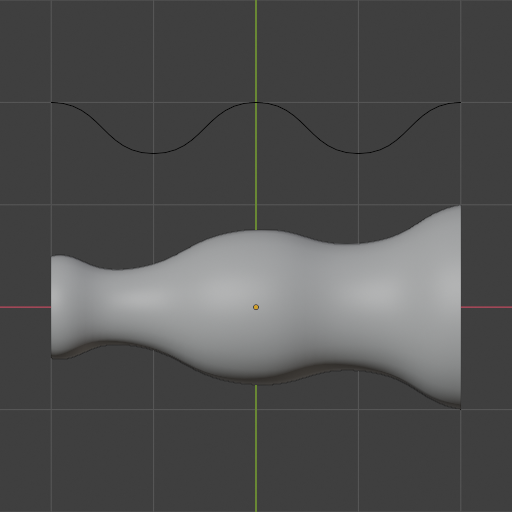
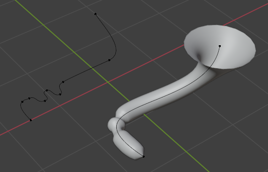
Taper
By selecting a 2D curve as the Taper Object of another (2D or 3D) curve, you can let the radius of the latter curve’s geometry vary over the curve’s length without having to create additional control points.
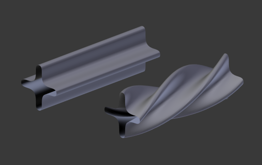
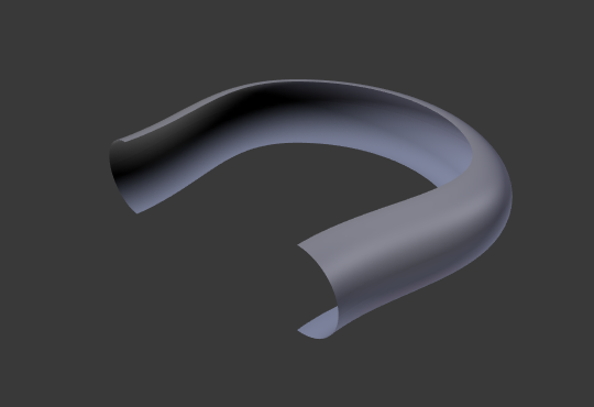
Tilt
You can use the Tilt tool to rotate a control point around its tangent axis, creating a twist in the curve. The example below also uses a custom profile (cross section).