Mesh Bevel Node
The Mesh Bevel Node allows you to bevel edges or vertices of a Mesh geometry. This node is very similar to the Bevel modifier but with some differences to fit better with the Geometry Nodes way of doing things. Some modifier options are omitted because they can be done with external helper node groups.
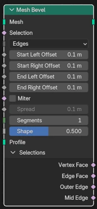
Inputs
- Mesh
Standard mesh input.
- Auswahl
A selection of which edges to bevel (if Affect Kind is Edges) or which vertices to bevel (if Affect Kind is Vertices).
- Affect Kind
- Edges:
Selected edges will be beveled.
Bemerkung
Only manifold edges (i.e., those attached to exactly two faces) will be beveled.
- Vertices:
Selected vertices will be beveled.
- Start Left Offset
The perpendicular offset into the left face of the beveled edge where the left side of the bevel starts. The left face is the one on your left if you stand on the edge’s origin, on the positive face normal side. Available when edge beveling.
- Start Right Offset
Similar to Start Left Offset, but for the start of the right side of the edge bevel. Available when edge beveling.
- End Left Offset
Similar to the Start Left Offset, but for the end of the left side of the edge bevel. Available when edge beveling.
- End Right Offset
Similar to the Start Left Offset, but for the end of the right side of the edge bevel. Available when edge beveling.
- Offset
The amount to slide along an edge away from a beveled vertex. Available when vertex beveling.
- Miter
A selection of which beveled edges should get a miter connection between it and the next counter-clockwise beveled edge attached to its vertex (at each end).
Bemerkung
In the bevel modifier, there is a choice between Sharp, Arc, and Patch miters, with separate choices for inner and outer miters, and these choices apply globally. In this bevel node, all inner miters, if selected, are Arc, and all outer miters, if selected, are Patch.
- Spread
The amount used to spread vertices apart, on inner miters.
- Segments
The number of edge loops added along a beveled edge’s face (if edge beveling), or the number of vertices added on the lines between edges (if vertex beveling).
- Form
The shape of the bevel, from concave to convex. It has no effect if Segments is less than 2.
- Profile
This input, when attached to a curve, says to use the curve instead of concave or convex shape that is usually used on edge bevels. The curve should be in the XY plane (i.e., z=0), and should go from (x=0,y=1) to (x=1,y=0). The curve will get divided into a number of pieces given by the Segments input.
Outputs
- Mesh
Standard geometry output.
- Vertex Face
A boolean field indicating the „vertex mesh faces“. These are the new faces that form around a bevel-invovled vertex, both for edge beveling and vertex beveling.
- Edge Face
A boolean field indicating the „edge mesh faces“. These are the new faces that go along the length of beveled edges, when edge beveling. There are no edge mesh faces when vertex beveling.
- Outer Edge
A boolean field indicating the new edges that are on the outside of the faces making up a beveled edge. If there is only 1 segment then these will just be the two edges of the beveled face quad that go along the original faces. If there is more than 1 segment then the inner edges between those two outer edges are skipped.
- Mid Edge
A boolean field indicating the edge that goes down the middle of the „edge mesh faces“. There is only a Mid Edge if there are 2 or more segments. If the number of segments is odd then there isn’t an exact middle, so the mid edge is rounded down from the middle.
Beispiele
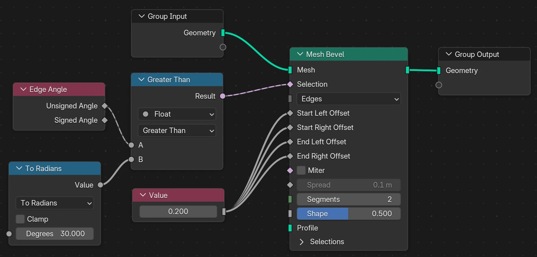
A number of controls are available in the bevel modifier but not in the bevel node. Most of these controls can be achieved by adding nodes in front of the inputs or after the outputs.
For example, to apply the Angle Limit Method control, we can make use of an Edge Angle node to measure the angle between the two faces attached to a manifold edge, and then compare that to a desired threshold and use the result of that comparison to select the edges to bevel.