Attributes
An attribute is a generic term to describe data stored per-element in a geometry data-block. For example, every vertex can have an associated number or vector. Attributes can be altered by connecting a value to the Group Output node, but also many nodes can change the values of specific attributes.
Note
Attribute data types and domains are converted implicitly where possible, just like node sockets.
Named Attributes
Named attributes are created and used in other areas of Blender like shaders, painting, and UV mapping. In the modifier panel, a named attribute can be used for input by clicking the icon to the right of the value button. The string input allows you to search and choose existing attributes from the modifier’s input geometry.
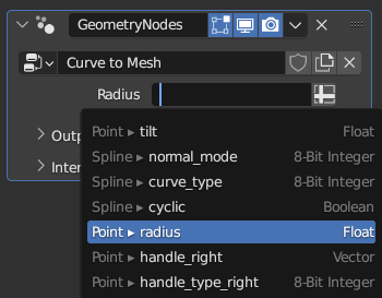
Attribute Search.
The attribute search gives a bit of context about each attribute. To the left of the menu, the attribute domain is shown followed by the attribute name. To the right of the menu, the attribute data type is shown.
Anonymous Attributes
The Normal and Rotation outputs are examples of attribute fields, which refer to an attribute stored on a geometry.
An anonymous attribute is a set of generic data stored on a geometry that doesn’t have a name. Usually, attributes exposed in Blender’s interface all have names. However, in geometry nodes, attributes can be passed around with node sockets. In these cases, an Attribute Field output is created, which is used by nodes to find attribute data in an input geometry.
Anonymous attributes are still stored on the geometry like other attributes, and they are even automatically interpolated when the geometry changes with other nodes, except for a few cases. So generally, if the node link is still accessible, the attribute it references will be available too. However, anonymous attributes cannot be connected to a completely separate geometry that was created from a different source. To transfer attributes between separate geometries, the Sample Index Node or other similar nodes like the Sample Nearest Surface Node can be used.
Attribute Data Types
The type of an attribute is the kind of data stored at each element.
- Float:
Single floating-point value, commonly used for weights or intensity values.
- Boolean:
True or false value for binary conditions.
- Integer:
32-bit integer, used for indices or discrete values.
- Vector:
3D vector with floating-point values, often representing directions or positions.
- Color:
RGBA color with 32-bit floating-point values, stored in linear Color Space. Suitable for high dynamic range and wide-gamut colors.
- Byte Color:
RGBA color with 8-bit positive integer values, useful for compact color storage. These are always stored in the sRGB Color Space. For wide gamut or linear workflows, use the Color type instead.
- String:
Text string for storing names or labels.
- 2D Vector:
Two dimension vector with floating-point values, often used for UV coordinates.
- 4D Vector:
Four dimension vector with floating-point values, often used for rotation quaternions.
- 8-Bit Integer:
Small integer with a range from -128 to 127.
- 2D 16-Bit Integer Vector:
Signed 16-bit 2D vector for compact storage of integer pairs.
- 2D Integer Vector:
Signed 32-bit 2D vector.
- Quaternion:
Floating-point Quaternion rotation used in 3D transformations.
- 4x4 Matrix:
Floating-point matrix used for transformations or storing spatial relationships.
The above list is in the order of least to most “complex” (An integer can contain more data than a boolean, so it is more complicated). When joining separate geometries together, the more complex data type is preferred when there are matching names. This is particularly important when joining geometry with named attributes with the Join Geometry Node.
To store 2D Vectors (UV maps) and Byte Colors the Store Named Attribute Node must be used because there are no sockets for those types.
Data Conversion
Through the use of Geometry Nodes, data can be converted between types.
Valid conversions:
Between color and vector – mapping between color channels and vector components.
Between color and float – the color data is converted to its grayscale equivalent.
Between float and integer – integers simply become floats, floats are truncated.
Between float and vector – when a float becomes a vector the value is used for each component. When a vector becomes a float the average of the components is taken.
Between float and boolean – values greater than 0 are true, true maps to 1, and false maps to 0.
Default-Initialization
Attributes always have a clearly defined value. In the case where the value of an attribute is read from a part of geometry on which its value hasn’t been specified prior to the read, the value of that attribute is default-initialized on that part of geometry. This applies whether that attribute is named or anonymous. The default-intialization value is dependant on the data type of that attribute:
- Float:
0
- Boolean:
False
- Integer:
0
- Vector:
(0, 0, 0)
- Color:
(0, 0, 0, 0)
- Byte Color:
(0, 0, 0, 0)
- String:
Empty string.
- 2D Vector:
(0, 0)
- 4D Vector:
(0, 0, 0, 0)
- 8-Bit Integer:
0
- 2D 16-Bit Integer Vector:
(0, 0)
- 2D Integer Vector:
(0, 0)
- Quaternion:
(1, 0, 0, 0)
- 4x4 Matrix:
Matrix with all components set to 0.
Attribute Domains
The domain of an attribute refers to what type of geometry element the attribute corresponds to. Knowing the domain of an attribute is important because it defines how it may be interpolated and used in nodes and shading. You can use the Spreadsheet Editor to determine the domains of attributes.
- Point domain attributes are associated with single locations in space with a position:
Vertices of a mesh
Points of a point cloud
Curve control points
Edge domain attributes are associated with the edges of a mesh.
Face domain attributes are associated with the faces of a mesh.
Face Corner domain attributes are associated with the corners of the faces of the mesh. An example is a UV map attribute.
Spline domain attributes are associated with a group of connected curve control points.
Instance domain attributes exist on the Instances in a geometry. They can be used to store different values on copies of geometry data. Instance domain attributes are only supported in geometry nodes.
Layer domain attributes are associated with a Grease Pencil Layer.
Attributes are automatically interpolated to other domains. For example, when the Position Node is connected to the selection input of the Set Material Node node, the values are interpolated from the Point domain to the Face domain. Normally, domain conversions use simple averages for values, but Boolean data type attributes have special rules for interpolation:
Boolean Domain Interpolation
From |
To |
Conversion |
|---|---|---|
Point |
Edge |
An edge is selected if both of its vertices were selected. |
Point |
Face |
A face is selected if all of its vertices were selected too. |
Point |
Corner |
Each corner’s value is simply a copy of the value at its vertex. |
Point |
Spline |
A spline is selected if all of its control points were selected. |
Edge |
Point |
A vertex is selected if any connected edge was selected. |
Edge |
Face |
A face is selected if all of its edges are selected. |
Edge |
Corner |
A corner is selected if its two adjacent edges were selected. |
Face |
Point |
A vertex is selected if any of the connected faces were selected. |
Face |
Edge |
An edge is selected if any connected face was selected. |
Face |
Corner |
Each corner’s value is simply a copy of the value at its face. |
Corner |
Point |
A vertex is selected if all connected face corners were selected and it is not a loose vertex. |
Corner |
Edge |
An edge is selected if all corners on adjacent faces were selected. |
Corner |
Face |
A face is selected if all of its corners were selected. |
Spline |
Point |
Each point’s value is simply a copy of the corresponding value of the spline. |
Built-In Attributes
Built-in attributes always exist, and cannot be removed. Their data type and domain cannot be changed.
Name |
Type |
Domain |
Notes |
|---|---|---|---|
|
Vector |
Point |
Built-in attribute describing vertex or point locations, in the local space of a geometry. Any node that changes the location of points will adjust this attribute, like the Transform Geometry Node and the Set Position Node. |
|
Float |
Point |
A built-in attribute on point clouds used to set the size for the points in the viewport. Also built-in on curves, where it controls the size of each curve control point when converted to a mesh, or for other operations. |
|
Integer |
Point |
Created by the Distribute Points on Faces to provide stability when the shape of the input mesh changes, and used on instances to create motion blur. Values are expected to be large, with no order. This attribute is used by nodes that generate randomness, like the Random Value Node. Unlike other built-in attributes, this attribute is not required, and can be removed. |
|
Integer |
Face |
Used to specify the material slot for every face in a mesh. |
|
Boolean |
Edge |
Attribute determining if an edge should have flat (rather than smooth) shading enabled in the viewport or a render. |
|
Boolean |
Face |
Attribute determining if a face should have flat (rather than smooth) shading enabled in the viewport or a render. |
|
Integer |
Spline |
Determines the number of evaluated points between two control points of a spline. Only NURBS and Bézier splines have this attribute, for poly splines, the value is always one. |
|
Boolean |
Spline |
Determines whether the spline has a segment that connects its first and last control points. |
|
Vector |
Point |
Describes the location of the left handle of a curve control point, on the side of the curve’s start. Only exists when the curve contains a Bézier spline. |
|
Vector |
Point |
Describes the location of the right handle of a curve control point, on the side of the curve’s end. Only exists when the curve contains a Bézier spline. |
Naming Conventions
These attributes do not exist by default, but are used implicitly by certain parts of Blender. The data type of these attributes can be changed, just like any attribute besides the built-in attributes. However, the attributes might be expected by Blender to have a certain type.
Name |
Type |
Domain |
Notes |
|---|---|---|---|
|
Float |
Point |
Used as vertex control for the bevel modifier. |
|
Float |
Edge |
Used as edge control for the bevel modifier. |
|
Float |
Edge |
Edge attribute used by the Subdivision Surface modifier. The values are expected to be in a range of 0 and 1. |
|
Float |
Point |
Vertex attribute used by the Subdivision Surface modifier. The values are expected to be in a range of 0 and 1. |
|
2D 16-Bit Integer Array |
Face Corner |
Used by Custom Split Normals for mesh objects. |
|
Boolean |
Edge |
Used by Edge Marks for mesh objects. |
|
Boolean |
Edge |
Used by Face Marks for mesh objects. |
|
Vector |
Point |
Holds the position of points or vertices from before a geometry is deformed procedurally. Can be created automatically before Shape Keys and Modifiers are evaluated with the Add Rest Position option. |
|
Integer |
Face |
Used by the Sculpt Face Sets Feature. |
|
Float |
Point |
Used by the Sculpt Masking Feature. |
|
2D Vector |
Curve |
Used to describe curve attachment locations on a mesh surface, typically used for the hair system. |
|
Boolean |
Edge |
True if an edge is considered a boundary between UV islands when unwrapping. |
|
Vector |
Point |
Used to create motion blur when rendering animations. |
Custom Attributes
Vertex groups, UV maps and Color Attributes are available as attributes in geometry nodes. They are referred to by their name. Naming collisions (e.g. a vertex group and a UV map with the same name) should be avoided. If there is a naming collision, only one of the attributes is accessible in geometry nodes.
Attributes with any other name can also be created by nodes, when the name is used for the first time.
Note that geometry nodes does not always produce e.g. vertex groups if a node like Join Geometry is used. Similarly, if the data type of a vertex group attribute is changed from the initial “Float” type, the attribute will no longer be a vertex group.
Attribute Conversion Operator
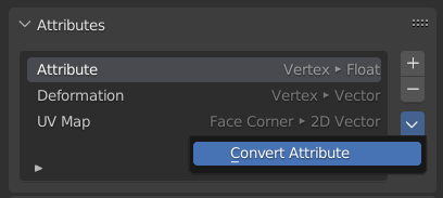
This operator found in the Attributes panel of the property editor can change the domain or data type of an attribute.
Due to ongoing development in the area of attributes, many areas of Blender can not yet work with the generic (identified with a name, stored on any domain with any data type) attributes used by geometry nodes. That makes this operator an essential workaround in some cases where existing tools must be used with data generated from geometry nodes.
- Mode
- Generic:
Interpolate and convert the attribute between the domains and data types described on this page.
- Vertex Group:
Create a Vertex Group from the attribute, which corresponds to a float attribute on the point domain.
Note
This operator only works on original object data, not including the results of modifiers, so any attributes added or changed by geometry nodes will not be affected. To change the type of an attribute generated procedurally, modifiers must be applied.