Extrude Faces
Reference
- Mode:
Edit Mode
- Menu:
,
- Shortcut:
E
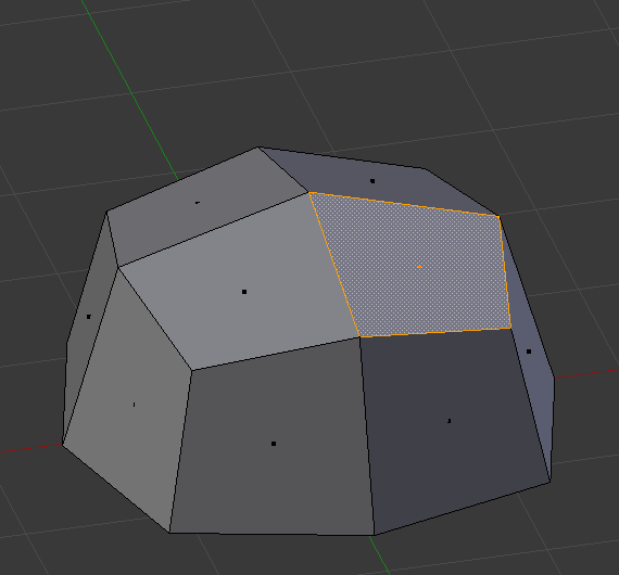
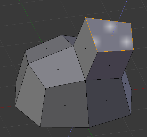
This tool creates new faces around the border of the selected faces, then allows moving the selected faces along an axis using the mouse. The result is an extrusion: a square gets turned into a box, a disc into a cylinder, and so on. This is used very often in modeling and can serve to add limbs to characters, branches to trees, and so on.
Once the faces are in place, press LMB or Return to confirm. Pressing RMB or Esc will cancel the move and leave the selected faces at their original location, but the newly created faces will still be there.
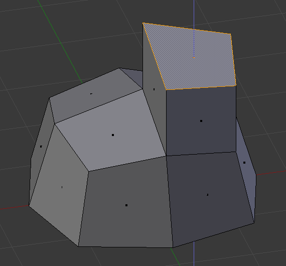
By default, the extrusion axis is the average of the face normals, but this Axis Locking can be changed by pressing an axis key (X, Y, or Z):
Press once to use the corresponding global axis.
Press twice to use the average of the faces’ local axes.
Press three times to disable axis locking (allows moving the faces anywhere).
After extruding, the following options are available in the Adjust Last Operation panel:
- Flip Normals
Flip the normals of the newly created faces, as they might be pointing the wrong way depending on the extrusion direction. See the Face Orientation overlay of the 3D Viewport to check whether they are correct.
- Dissolve Orthogonal Edges
When enabled, newly created faces will be merged with surrounding existing faces (potentially turning them into n-gons) if they form a flat surface together.
- Orientation
Determines the extrusion axis to use.
- Mirror Editing
Enabling this option moves the corresponding faces on the other side of the mesh without extruding them, making it not very useful here.
- Proportional Editing
Enabling this option moves the surrounding unselected faces together with the extruded ones, making it not very useful here.