Solidify Modifier
The Solidify modifier takes the surface of any mesh and adds depth, thickness to it.
Options
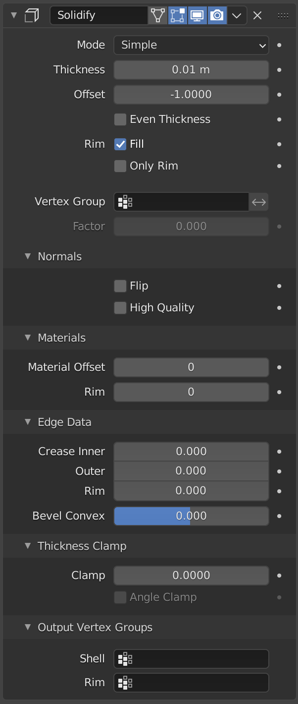
- Mode
- Simple:
This is the default solidify algorithm, which simply extrudes the geometry. This algorithm does not work on geometry where edges have more than two adjacent faces.
Important
If the normals of adjacent faces don’t point into the same general direction, simple mode will not be able to solidify the boundary between those. This happens if the normals are not recalculated or for example on one-sided surfaces like a Möbius strip.
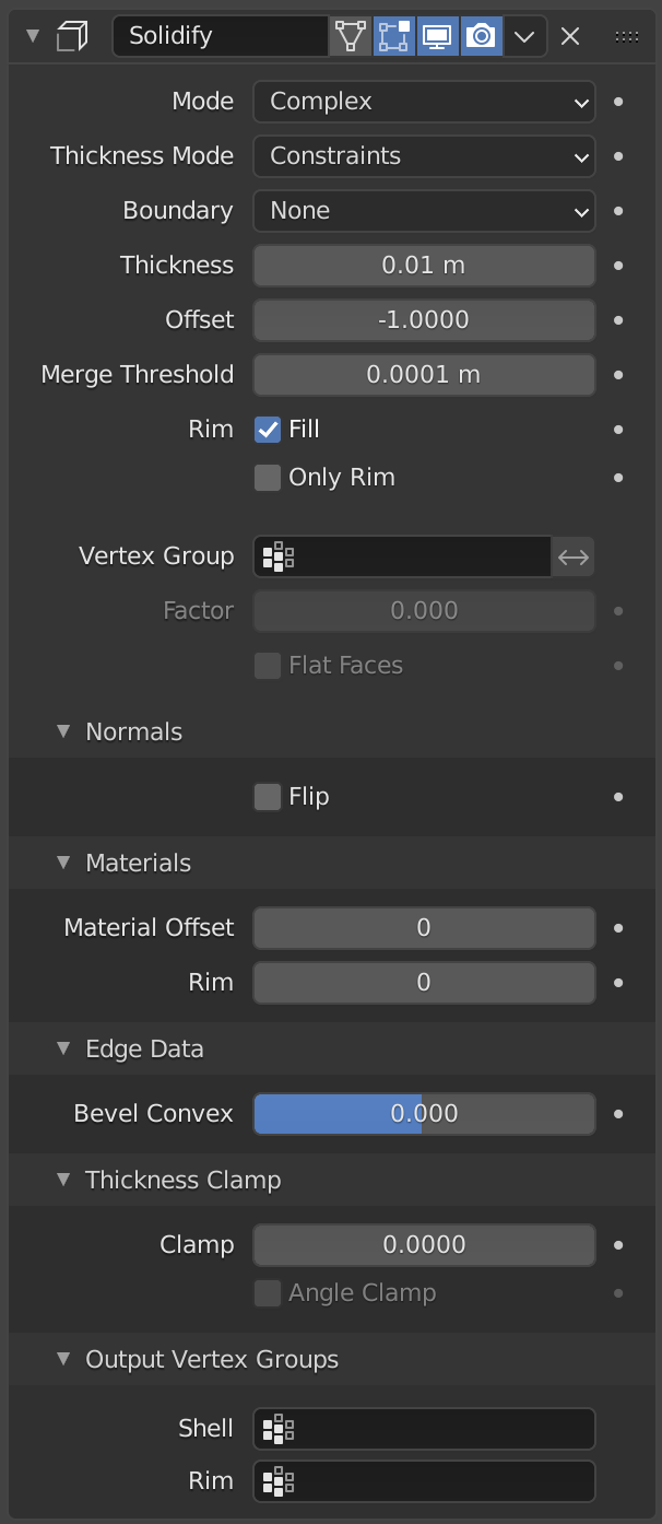
- Complex:
This is a solidify algorithm which can handle every geometric situation to guarantee a manifold output geometry. This algorithm is able to solidify shapes like Möbius strips, Klein bottles, architectural wall layouts and many more which the Simple Mode isn’t able to do. If the special cases are not present it is recommended to choose Simple because the extra logic makes this algorithm much slower.
Note
There are no options for crease in the Modifier tab because crease is handled in a dynamic way. The modifier will transfer the creases of the original mesh in a smart way to the output mesh to work with the Subdivision Surface modifier.
- Thickness Mode Complex Mode
Choose the kind of thickness handling (thickness solver).
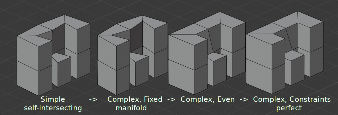
Different thickness options on a non-manifold mesh.
- Fixed:
This is similar to Simple Mode without Even Thickness. The new vertices are always in a fixed distance to the old ones.
- Even:
This is similar to Simple Mode with Even Thickness and High Quality Normals. It adjusts for sharp corners, but may not always work when more than three faces come together.
- Constraints:
This is a more advanced model to try to always get the optimal thickness everywhere. For up to three faces it is always guaranteed to find an optimal solution.
- Boundary Complex Mode
Choose the kind of boundary that suits the model the most.
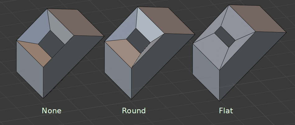
Different boundary options with a matCap.
- None:
No boundary fix is applied. Results are stable.
- Round:
Adjusts the boundary for an opening to face inwards (like a hole in an egg).
- Flat:
Adjusts the boundary of a planar opening to be a flat (like a cut sphere).
- Thickness
The depth to be solidified.
- Offset
A value between (-1 to 1) to locate the solidified output inside or outside the original mesh. The inside and outside is determined by the face normals. Set to 0.0, the solidified output will be centered on the original mesh.
- Even Thickness Simple Mode
Maintain thickness by adjusting for sharp corners. Sometimes improves quality but also increases computation time.
- Merge Threshold Complex Mode
Distance within which degenerated geometry is merged.
- Rim – Fill
Creates edge loops and faces between the inner and outer surfaces on face edges (slow, disable when not needed).
- Only Rim
Simple Mode: Only leaves the extruded surface and the generated perpendicular rim.
Complex Mode: Only leaves the generated perpendicular rim.
- Vertex Group
The weights of the selected vertex group are multiplied onto the Thickness, so vertices with lower weights will be less thick. The vertices which are not part of the vertex group will be used as if their weight was zero.
- Invert
Reverses the vertex group weights, so that the used weight is one minus the actual weight.
- Factor
How much the vertex weights are taken into account.
On 0.0 , vertices with zero weight will have no thickness at all.
On 0.5 , vertices with zero weight will be half as thick as those with full weight.
On 1.0 , the weights are ignored and the Thickness value is used for every vertex.
- Flat Faces Complex Mode
Use the minimal vertex weight assigned to the vertices of a face to make sure that new faces stay parallel to their original ones. This is slow, so disable it when it is not needed.
Note
If the final thickness of a vertex is zero, it will still be solidified. Therefore creating duplicate geometry, which sometimes needs extra care.
Normals
- Flip Normals
Reverse the normals of all geometry (both the inner and outer surfaces).
- High Quality Normals Simple Mode
Normals are calculated to produce a more even thickness. Sometimes improves quality but also increases computation time.
Materials
- Material Offset
Choose a different material slot index to use for the new geometry. This is applied as an offset from the original material of the face from which it was solidified.
A value of 0 means it will use the same material.
A value of 1 means it will use the material immediately below the original material.
A value of -2 means the material two positions above the original material will be used.
These are clamped to the top-most and bottom-most material slots.
- Rim
Similarly, you can give another material to the rim faces.
Edge Data
- Inner Simple Mode
Set a crease to the inner edges.
- Outer Simple Mode
Set a crease to the outer edges.
- Rim Simple Mode
Set a crease to the rim.
- Bevel Convex
Edge bevel weight to be added to outside edges.
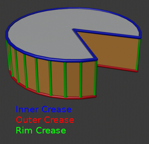
Edges which will get creases marked.
Thickness Clamp
- Clamp
A value between (0 to 2) to clamp offsets to avoid self-intersection. The amount is determined by the length of the shortest adjacent edge.
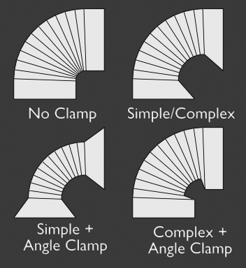
Clamp Offset.
- Angle Clamp
If enabled clamping will also consider angles in the geometry, not only lengths.
Output Vertex Groups
- Shell
Vertex group that the generated shell geometry will be weighted to. This allows you to use other modifiers to only affect the shell geometry by using that modifier’s vertex group influence control.
- Rim
Same as Shell Vertex Group, but for the generated rim geometry.
Known Limitations
Even Thickness
Solidify thickness is an approximation. While Even Thickness and High Quality Normals should yield good results, the final wall thickness is not guaranteed and may vary depending on the mesh topology. Especially for vertices with more than three adjacent faces.
In order to maintain a precise wall thickness in every case, we would need to add/remove faces on the offset shell, something this modifier does not do since this would add a lot of complexity. The best option to preserve wall thickness is complex mode with constraints thickness mode, but it is also not guaranteed to work perfect in every case.