Data Transfer Modifier
The Data Transfer modifier copies certain types of data from an external mesh to the modified one. This could be UV maps, color attributes, custom normals, and so on.
For each element (vertex/edge/face) in the modified mesh, the modifier finds one or more matching elements in the source mesh, then interpolates between those source elements’ values.
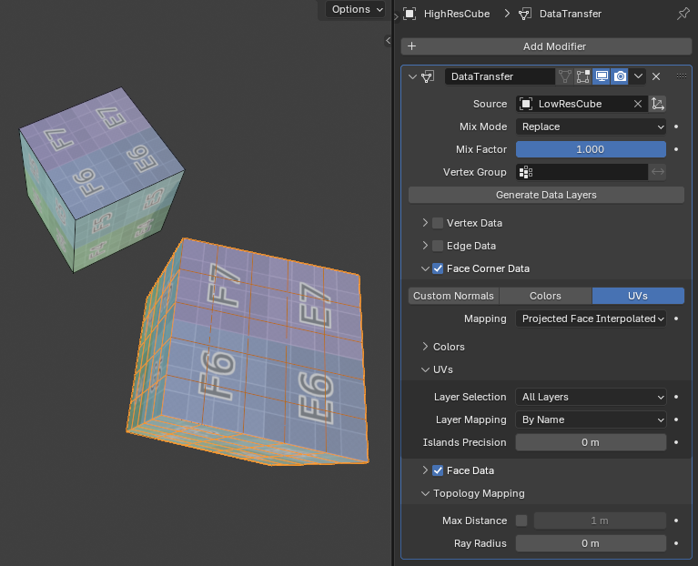
Transferring a UV map from a low resolution mesh to a high resolution one using interpolation.
See also
Usage
Select the Source mesh you want to copy data from.
If the source mesh and modified mesh aren’t overlapping in world space, uncheck Object Transform (the axes icon next to the source mesh).
Select which type of data you want to copy (e.g. vertex groups, UV maps…).
If you only want to copy a specific vertex group/UV map/…, select it in Layer Selection.
If the vertex groups/… you want to copy don’t exist yet on the modified mesh, click Generate Data Layers to create them.
Options
- Source
Mesh object to copy data from.
- Object Transform
Whether to take into account the world space transformations of the source and destination objects. When unchecked, the modifier acts like both objects are in the same position and have the default rotation and scale.
- Mix Mode
How to combine the new data from the source mesh with the original data in the destination mesh.
- Replace
Interpolate between the original and new value using Mix Factor.
- Above Threshold
Replace the destination value if it’s greater than or equal to Mix Factor. In the case of multi-component data like colors, the threshold is compared to the average of these components.
For boolean data like Freestyle Mark, you can use this to perform a logical AND: simply ensure the Mix Factor is 0.5 or greater, and the destination mesh will only have marked edges/faces that were already marked and are also marked in the source mesh.
- Below Threshold
Replace the destination value if it’s less than or equal to Mix Factor. In the case of multi-component data like colors, the threshold is compared to the average of these components.
For boolean data like Freestyle Mark, you can use this to perform a logical OR: simply ensure the Mix Factor is 0.5 or greater, and the destination mesh will have marked edges/faces that were already marked or are marked in the source mesh.
- Mix
Mix the source value with the destination value, e.g. performing an alpha blend in the case of color attributes. Then, interpolate using Mix Factor.
- Add
Add the source value to the destination value, then interpolate using Mix Factor.
- Subtract
Subtract the source value from the destination value, then interpolate using Mix Factor.
- Multiply
Multiply the source value by the destination value, then interpolate using Mix Factor.
- Mix Factor
Interpolation factor between the original destination value and the newly calculated value. If Mix Mode is Above Threshold or Below Threshold, this is a threshold value instead.
- Vertex Group
Allows per-element control of the Mix Factor.
- Invert
Invert the weights of the vertex group (change them to 1 - weight).
- Generate Data Layers
Click to add any missing data layers, e.g. vertex groups that exist on the source mesh but not yet on the modified mesh. The modifier doesn’t do this automatically, so make sure to click this button (or add the missing layers yourself) as the transfer may not work otherwise.
Layers added this way will stay behind when removing the modifier.
- Data Types
The toggle buttons Custom Normals, Colors, UVs etc. indicate which data should be transferred.
- Mapping
How to find the matching source element(s) for each destination element. The various options are explained in the Mapping section below.
- Layer Selection
Which source layers to copy to the destination mesh (e.g. all vertex groups or a specific vertex group).
- Layer Mapping
How to find the destination layer for a given source layer: by name or by order.
- Islands Precision
Controls the calculation that prevents a destination face from receiving UV coordinates from disparate source UV islands (areas bordered by seams). Keeping this at 0.0 means no island handling at all, while higher numbers increase the correctness of the result at the cost of extra computation.
Typically, small values like 0.02 are enough to get good results, but if you are mapping from a very high-poly source towards a very low-poly destination, you may have to raise it quite significantly.
Mapping
Topology
Simply matches the elements based on their index. This requires both meshes to have the same number of elements and those elements to be ordered in the same way. Best suited for a destination mesh that’s a deformed copy of the source.
See also
Sort Elements to ensure the objects have the same element ordering.
One-To-One Mappings
These mappings always select only one source element for each destination one.
- Vertex Data
- Nearest Vertex
Use the nearest source vertex.
- Nearest Edge Vertex
Use the nearest source vertex on the nearest (by midpoint distance) source edge.
- Nearest Face Vertex
Use the nearest source vertex on the nearest (by midpoint distance) source face.
- Edge Data
- Nearest Vertices
Use the source edge whose vertices are nearest to the destination edge’s.
- Nearest Edge
Use the source edge whose midpoint is nearest to the destination edge’s.
- Nearest Face Edge
Use the nearest source edge on the nearest face (both by midpoint distance).
- Face Corner Data
A face corner is a vertex in the context of a face. This concept is most commonly used in UV maps: each face corner can have its own UV coordinate, or in other words, one 3D vertex can correspond to several UV vertices (one per face).
- Nearest Corner and Best Matching Normal
Use the source corner that’s nearest to the destination corner and has the most similar split normal.
- Nearest Corner and Best Matching Face Normal
Use the source corner that’s nearest to the destination corner and has the most similar face normal.
- Nearest Corner of Nearest Face
Use the nearest source corner on the nearest source face.
- Face Data
- Nearest Face
Use the nearest source face (by midpoint distance).
- Best Normal-Matching
Cast a ray from the destination face’s centerpoint along the face’s normal and use the source face found this way.
Interpolated Mappings
These mappings can match several source elements and interpolate between their values.
- Vertex Data
- Nearest Edge Interpolated
Find the nearest point on the nearest source edge, then use that point to interpolate between the values of the edge’s vertices.
- Nearest Face Interpolated
Find the nearest point on the nearest source face, then use that point to interpolate between the values of the face’s vertices.
- Projected Face Interpolated
Project the destination vertex along its normal onto a source face, then use the projected point to interpolate between the values of the face’s vertices.
- Edge Data
- Projected Edge Interpolated
Find source edges by projecting from a number of points on the destination edge (where each point is projected along the interpolated normals of the destination edge’s vertices). Then, interpolate between the values of the source edges found this way.
- Face Corner Data
- Nearest Face Interpolated
Find the nearest point on the nearest source face, then use that point to interpolate between the values of the face’s corners.
- Projected Face Interpolated
Project the destination corner along its normal onto a source face, then use the projected point to interpolate between the values of the face’s corners.
- Face Data
- Projected Face Interpolated
Find source faces by casting rays from a number of points on the destination face along the destination face’s normal. Then, interpolate between the values of these source faces.
Topology Mapping
Note
Despite the name of this panel, these settings do not apply to the Topology mapping type.
- Max Distance
When the checkbox is enabled, source and destination elements that are further away from each other than the specified distance will not be considered as matches.
- Ray Radius
The starting radius to use when ray casting.
For certain mapping types, the operator performs a series of ray casts from each destination element to find matching source elements. These ray casts start with the specified radius and grow progressively larger until a match is found or a limit is reached.
A low starting radius will give more accurate results, but has worse performance if it’s too small and needs to be increased. A high starting radius has better performance, but may result in suboptimal matches.
In general, use a low radius for dense source meshes and a high one for simple ones.