Cloth Dynamics
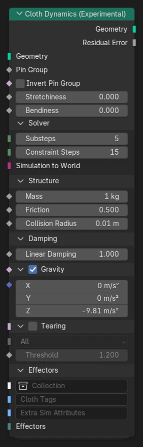
The Cloth Dynamics node simulates cloth physics on mesh surfaces.
Cloth movement is simulated using the XPBD Solver node. The Cloth Dynamics node takes care of setting up the necessary structural constraints and common effectors, such as gravity, damping, and collision. Additional effects can be added through typed bundles.
Warning
Physics simulation for cloth dynamics is an experimental feature and may change significantly in the future. Some features are currently missing, such as self-collision.
Inputs
- Geometry
Mesh geometry that should be animated or simulated. This is used as the rest shape for generating internal stretching and bending forces.
- Pin Group
Weights for pinning vertices to their rest position. A value of 1 will keep a vertex fixed, while values less than 1 create soft pinning that allows deviation from the rest position.
- Invert Pin Group
Uses one minus the Pin Group weight for points where this field is true.
- Stretchiness
Factor describing the amount of stretching allowed for edge relative to their rest length. A stretchiness factor of 0 does not allow any stretching.
- Bendiness
Factor describing the amount of bending allowed between faces relative to their rest shape. A bendiness factor of 0 does not allow any bending around the shared edge.
Solver
General settings for the physics solver.
- Substeps
Number of substeps used by the simulation. Increasing substeps can help improve stability in some cases, but also increases cost due to repeated collision detection.
- Constraint Iterations
Number of iterations performed by the constraint solver to ensure all constraints are satisfied. If the residual error is larger than 1 then increasing the constraint iterations is recommended.
- Simulation to World
Optional transform from object space into simulation space. This defines the space in which all physical simulation takes place. If no transform is specified the object should usually be stationary.
Structure
Configure the internal physical properties of cloth geometry.
- Mass
Mass attribute of curve points.
This value does not have to be “realistic” based on physical cloth weight, but should be considered an influence factor for external forces. Extreme values can lead to numerical instability.
- Friction
Coefficient for static and dynamic friction. Small friction coefficients model a slippery material while larger values create sticky behavior.
The exact meaning of the coefficient can be understood as the tangent of the friction angle (wikipedia): When the angle of the contact force to the surface normal is small the contact is in static friction and sticks the surface. Once the contact force exceeds the friction angle it enters dynamic friction and slows down proportional to the tangential velocity.
- Collision Radius
Distance margin for collision contacts, creating an additional offset between the cloth mesh and external colliders.
Damping
- Linear
Simple general damping feature that reduces velocity of any moving point, emulating drag in air or another medium. Damping coefficients describe the relative reduction of velocity per second, approximating exponential damping.
Gravity
Enable gravity.
- Gravity
Acceleration vector in simulation space, typically in negative Z direction.
Tearing
Enable cloth tearing, which splits the mesh along edges where stretching forces become too large.
- Mode
Chose which edges are allowed to tear.
- All:
Any edge can be split.
- Custom:
Only allow splitting edges included in the Edge Group.
- Voronoi:
Generate islands using a Voronoi pattern, only split edges between islands.
- Edge Group Custom
Group of edges that are allowed to tear.
- Voronoi Scale: Voronoi
Scale of the voronoi pattern used to generate untearable islands.
- Threshold
Edge length threshold at which tearing will occur. This describes the relative strain of the cloth, with equivalent stress depending on the stretchiness factor.
Effectors
Additional external effectors to add to the simulation. Effectors can be external force fields, colliders, or custom effectors that get executed at some stage of the simulation (see Custom Effector)
- Collection
A collection of objects with effectors.
Effectors can be added to object geometry using the Set Effector node.
- Cloth tags
Filter tags to set on the cloth geometry. These tags can be used to limit effectors, in case an effector is used in multiple simulation contexts.
- Effectors
A bundle of locally defined effectors. These can be created in a node tree and passed directly into the simulation node.
Outputs
- Geometry
Cloth geometry after deformation by physics.
- Residual error
Average relative error at the end of the last substep. This indicates the quality of the simulation:
An error value of 1 or less is considered a good result.
If the error is consistently greater than 1 the solver may need more constraint iterations, and possibly more substeps, to yield an accurate result.
If the error value exceeds 1 only in certain situations it can indicate an over-constrained simulation, for example due to overlapping colliders or extreme forces.
If the value is very small then the number of iterations or substeps is unnecessarily large and performance can be improved by lowering the iteration count.
Note
The relative error is based on threshold values defined for each constraint type. These thresholds are not currently exposed by the node asset and are fixed at 1 millimeter for distance-based constraints. The final value is computed as the root mean square of the sum of all relative constraint errors.
Common Issues
Insufficient constraint iterations
The more complex a simulation setup becomes, the more Constraint Iterations the solver needs to arrive at a correct solution. A simulation with insufficient iterations can look physically plausible, but can exhibit much more stretching and bending than should be expected.
Check the Residual Error value to confirm that the solution is accurate enough. The value should ideally not exceed 1.
Open collider boundaries
Only colliders with closed meshes are supported at this point. A collider must be a manifold mesh (no open boundaries), at least in areas where collision is expected.
Collider meshes with open boundaries can lead to sudden jumping. A point can move around an open boundary without generating a contact and approach a mesh face from the back. When it gets close to the mesh a contact is then suddenly detected and the point gets ejected from the mesh.
Example bug report: #159657.
Tunneling through colliders
Fast moving geometry may not reliably collide with thin meshes (“tunneling”).
Colliders must have a certain thickness to avoid tunneling, depending on the speed of collision and the number of substeps: with more substeps thinner colliders are possible, up to a certain point (see Too many substeps).
Too many substeps
Using too many substeps can lead to numerical errors, resulting in sudden changes of constraint response with changing stretchiness or bendiness. It is recommended to keep Substeps below 20 and instead increase the Constraint Iterations if more accuracy is needed.
The root cause is multiplicative factors using the inverse square of the time (sub)step, leading to rounding errors.