Mesh Structure
With meshes, everything is built from three basic elements: vertices, edges and faces.

Exemplo de estrutura de malha.
Vértices
The most elementary part of a mesh is the vertex (vertices plural) which is a single point or position in 3D space. Vertices are represented in the 3D Viewport in Edit Mode as small dots. The vertices of an object are stored as an array of coordinates.
Dica
Do not mistake the object origin for a vertex. It may look similar, but it is bigger and cannot be selected.
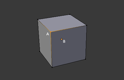
The vertex is labeled as «A»; the object’s origin dot is labeled as «B».
Arestas
An edge always connects two vertices by a straight line. The edges are the «wires» you see when you look at a mesh in wireframe view. They are usually invisible on the rendered image. They are used to construct faces.
Faces
Faces are used to build the actual surface of the object. They are what you see when you render the mesh. If this area does not contain a face, it will simply be transparent or nonexistent in the rendered image.
Uma face é definida como uma área entre tanto três (triângulos), quatro (quadriláteros) ou mais (multiláteros ou «n-gons») vértices , com uma aresta em cada lado. As faces são muitas vezes abreviadas a tris, quads & n-gons.
Triângulos são sempre planos e portanto fáceis de calcular. Por outro lado, quadrados deformam bem e são portanto preferidos para animação e modelagem por subdivisão.
Normais
In geometry, a normal is a direction or line that is perpendicular to something, typically a triangle or surface but can also be relative to a line, a tangent line for a point on a curve, or a tangent plane for a point on a surface.
Normals help to determine the shading of the mesh among other things.
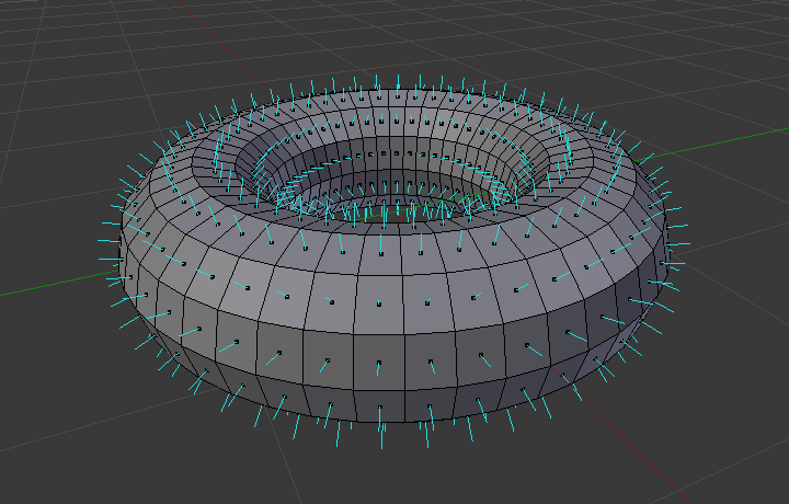
A visualization of the face normals of a torus.
In the figure above, each blue line represents the normal for a face on the torus. The lines are each perpendicular to the face on which they lie. The visualization can be activated, in Edit Mode, in the Mesh Display Viewport Overlays panel.
Shading
Surface normals play a fundamental role in determining how light interacts with 3D objects and thus greatly influence the shading of those objects. Normals can be shaded smooth or flat.
When a mesh uses flat shading, the faces are rendered and displayed uniformly. This is usually desirable for objects with flat surfaces such as a cube or pyramid.
When a mesh uses smooth shading, the normals are interpolated across the vertices of a polygonal mesh, smooth transitions between adjacent polygons can be achieved, resulting in a more realistic appearance.
By default face normals have flat shading however, this can be adjusted either for the whole object or per face.
To adjust the shading of the whole object, use:
Shade Smooth – To mark the whole object as smooth.
Shade Auto Smooth – To mark portions of the object as smooth.
To revert to flat shading, use Shade Flat.
The shading of objects can also be adjusted per face, edge, or vertex.
Custom Split Normals
Custom split normals are a way to tweak/fake shading by pointing normals towards other directions than the default, auto-computed ones. It is mostly used in game development, where it helps counterbalance some issues generated by low-poly objects (the most common examples are low-poly trees, bushes, grass, etc. and the “rounded” corners).
Blender supports custom normals on a “smooth fan” base, defined as a set of neighbor face corners sharing the same vertex and “linked” by smooth edges. This means you can have normals per face corners, per a set of neighbor face corners, or per vertex.
Custom split normal data is stored as the custom_normal
Attribute on the face corner Domain.
Dica
The computation of custom split normals can be disabled to improve performance. This option can be found in the Simplify Rendering Settings.
Free Normals
Free normals are a type of custom normal stored directly as direction vectors in object space. Unlike traditional custom normals, which are defined relative to the surrounding geometry (known as tangent or corner fan space), free normals are independent of mesh topology and do not rely on smooth groups or edge connectivity.
Because they are simple vectors, free normals are:
Efficient: Fast to evaluate, significantly improving viewport performance compared to tangent space normals.
Lightweight: Require less memory, especially beneficial for dense or heavily instanced meshes.
Static: They do not automatically update when the mesh is deformed (e.g. through modifiers or animations), so they are best suited for static geometry or cases where performance is critical.
Free normals can be assigned using the Set Mesh Normal Node in Free mode, and stored on the vertex, face, or face corner domain depending on the desired granularity.
Editing Custom Split Normals
Referência
- Mode:
Edit Mode
- Menu:
Painel:
- Atalho:
Alt-N
There are a number of tools for editing custom split normals. The custom normal mesh edit tools can affect all normals (the default), or only selected ones. To select a custom normal associated with a particular vertex and face:
Make the element selection mode both Vertex and Face (use Shift-LMB to enable the second one).
Select one or more vertices, then select a face. This can be repeated to select more vertices and a different face and so on. It is easiest to see the effect of these tools if you turn on the Edit Mode Overlays option Display vertex-per-face normals as lines.
Veja também
Importing Custom Split Normals
Some tools, particularly those used in CAD, tend to generate irregular geometry when tessellating their objects into meshes (very thin and long triangles, etc.). Auto-computed normals on such geometry often gives bad artifacts, so it is important to be able to import and use the normals as generated by the CAD tool itself.
Nota
Currently, only the FBX Importer and Alembic Importer are capable of importing custom normals.
Topologia
Anéis
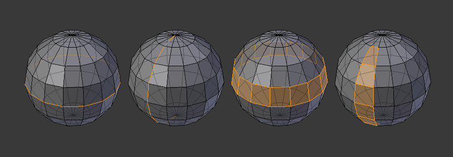
Anéis de arestas e faces.
Os anéis de arestas e faces sã conjuntos de arestas e faces que formam «anéis» contínuos como mostrados na Fig. Anéis de arestas e faces..
In the image above, loops that do not end in poles are cyclic (1 and 3). They start and end at the same vertex and divide the model into two partitions. Loops can be a quick and powerful tool to work with specific, continuous regions of a mesh and are a prerequisite for organic character animation. For a detailed description of how to work with loops in Blender, see: Select Loops.
Nota
Note que os anéis (2 e 4) não dão a volta completa em torno de todo o modelo. Os anéis param nos chamados polos pois não há uma única maneira de continuar um anel a partir de um polo. Os polos são vértices que estão conectados a três, cinco ou mais arestas. Da mesma maneira, vértices conectados a exatamente uma, duas ou quatro arestas não sã polos.
Anéis de arestas
Os anéis (1 e 2) na Fig. Anéis de arestas e faces. são anéis de arestas. Eles conectam vértices de maneira que cada um dos que estão no anel tenha exatamente dois vizinhos que não estão no anel e que estão posicionados em ambos os lados do anel (exceto os vértices inicial e final, no caso dos polos).
Os anéis de aresta são um conceito importante, especialmente em modelagem de orgânicos (com subdivisão de superfícies) e animação de personagens. Quando usados de maneira correta, eles permitem que você construa modelos com relativamente poucos vértices que parecem bastante naturais quando usados como superfícies de subdivisão e que são deformados muito bem durante as animações.
Take Fig. Anéis de arestas e faces. in organic modeling as an example: the edge loops follow the natural contours and deformation lines of the skin and the underlying muscles. The loops are denser in areas that deform more when the character moves, for example at the shoulders or knees.
Further details on working with edge loops can be found in Select Loops.
Anéis de faces
Estes são uma extensão lógica dos anéis de arestas já que estes consistem nas faces entre dois anéis de arestas, como mostrado nos anéis (3 e 4) na Fig. Anéis de arestas e faces.. Note que para anéis não circulares (4) as faces que contém os polos não são incluídas no anel de faces.
Detalhes adicionais sobre como trabalhar com os anéis de faces podem ser encontrados em Seleção de Anéis de Faces.
Poles
See N-poles & E-poles.
Non-Manifold
See Non-manifold.