Fields
Fundamentally, a field is a function: a set of instructions that can transform an arbitrary number of inputs into a single output. A field’s result can then be calculated many times with different input data. They are used all over geometry nodes to allow calculations that have different results for every element (mesh vertices, faces, etc.).
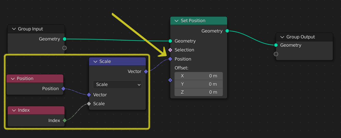
A field input to a node.
For example, in the figure above, the field connected to the “Set Position” node depends on two inputs, Position and Index, and transforms them into a vector using a single instruction.
Field Visualization
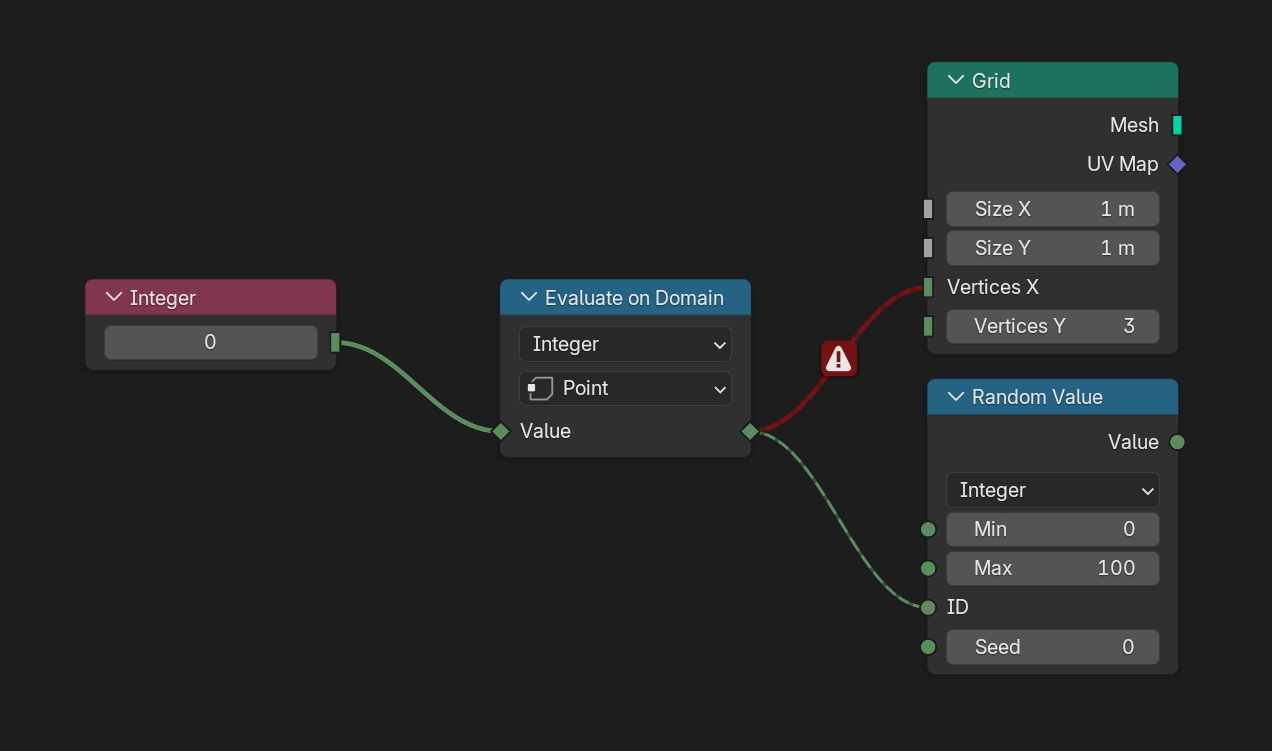
If a node connection is coming from a field socket, it will be drawn as a dashed line. Otherwise, it will be drawn as a solid line instead.
If you make the mistake of connecting a non-field socket to a field socket, the connection will be drawn as a solid red line indicating that there is an error.
팁
Often it is desired to extract a single value from a field. While it doesn’t make sense conceptually to simply change a field into a single value, the Sample Index Node or the Attribute Statistic Node can be used to retrieve a single value from a field evaluated on a geometry.
Node Types
Nodes can be separated into two categories: data flow nodes that usually pass geometry, and field nodes that operate on data per-element. Field nodes can be input nodes that bring geometry data into the node tree, or function nodes that operate on that data.
Data Flow Nodes
Nodes with a geometry input and a geometry output will almost always be data flow nodes. Meaning that they actually change geometry data that will be outputted from the Geometry Nodes modifier.
Function Nodes
Nodes with diamond socket inputs and outputs are field nodes, and resemble the instructions that will be evaluated by data flow nodes. Examples of function nodes are the math nodes and also more complex nodes like the Geometry Proximity Node.
Input Nodes
Input nodes provide data to the field evaluation process. By themselves, they mean nothing; they must be evaluated within the context of a data flow node (geometry) to actually output a value. Examples of input nodes are the built-in attribute input nodes like Position and ID, but also selection nodes like Endpoint Selection.
Field inputs may also come from other nodes that process geometry like the Distribute Points on Faces, in the form of Anonymous Attributes.
Field Context
All field nodes work in the context of the data flow node they are connected to. The context usually consists of a geometry component type and an attribute domain, so it determines what data is retrieved from input nodes.
One common misunderstanding is that the same field node tree used in multiple places will output the same data. This is not necessarily true, because the field node tree will be evaluated for every data flow node, potentially retrieving data from a different or changed geometry.
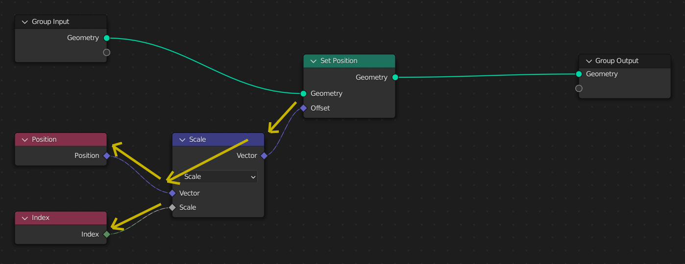
Here, the Set Position node’s input field is evaluated once. To evaluate the field, the node traverses backwards to retrieve the inputs from the field input nodes.
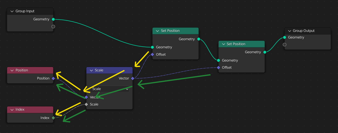
When a second Set Position node is added, the same field node tree is evaluated twice, once for each data flow node. At the second Set Position node, the results will be different since its geometry input will already have the changed position from the first node.
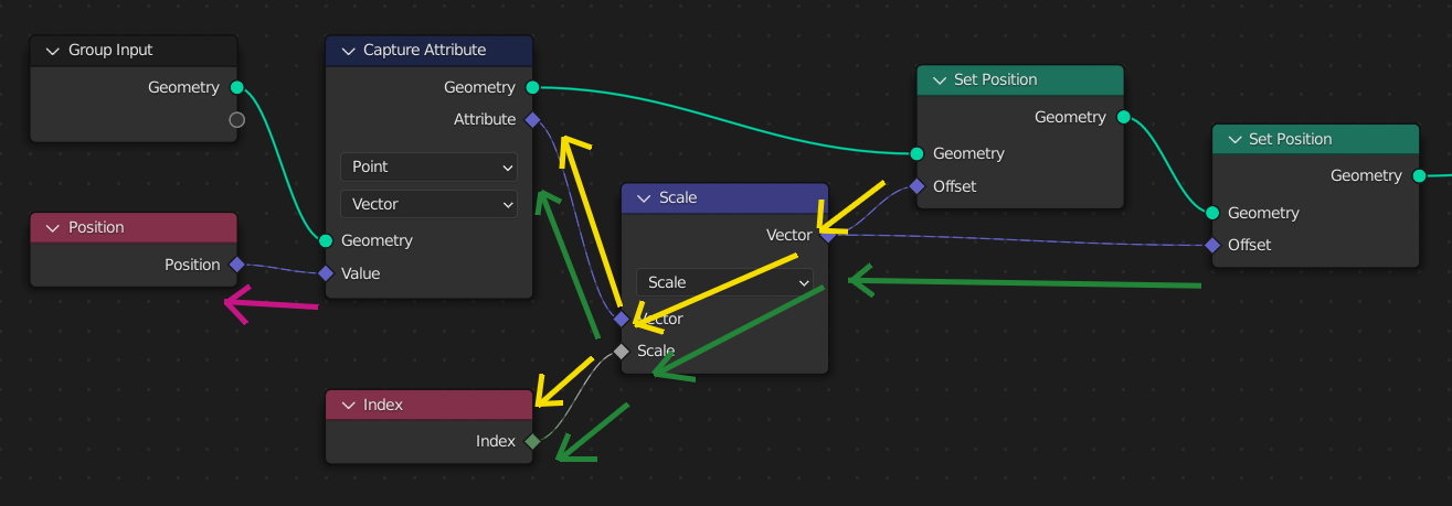
However, often it’s necessary to use the same field values even after changing the geometry. The Capture Attribute Node evaluates a field, copying the result to an anonymous attribute on the geometry.
Here, a Capture Attribute node stores a copy of the initial position. Notice that evaluating the field input of the Capture Attribute node is an entirely different step. Later on, the input fields to the Set Position nodes don’t use the actual position, but the anonymous attribute copy of it.