Gizmos
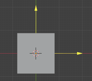
Grid with gizmo in the 3D viewport.
Gizmos allow changing inputs of Geometry Nodes directly in the 3D viewport. This is often more intuitive than controlling the inputs in the modifier or node editor.
Using Gizmos
Node inputs that can be controlled with a gizmo have an additional icon. The gizmos of that node are shown if it is selected. Clicking on the icon pins the gizmo, so that it is shown even if the node is not selected. Modifying the gizmo in the 3D viewport, modifies the value in the socket.
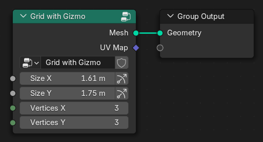
Example of a node group that has gizmos.
참고
Built-in nodes do not have their own gizmos yet. It’s possible to create node groups that have gizmos though.
Gizmos are often automatically propagated when an input socket with a gizmo is linked. The gizmo then controls the value that it is propagated to, instead of the input of the node group directly. Not all nodes support propagating gizmos, but many math operations do. A double link indicates that the propagation was successful.
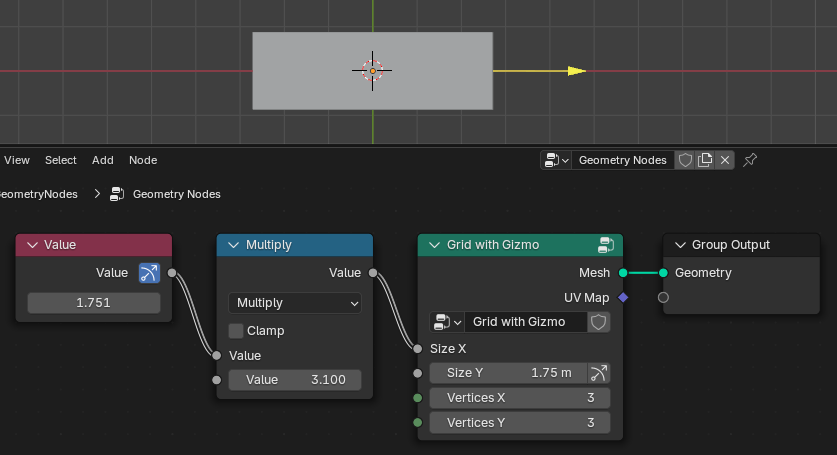
The gizmo is propagated from the Size X input socket to the Value node.
Gizmos can also be propagated to Group Inputs, in which case they are also available on the parent group node. If the current group is used by a modifier directly, the gizmo will also be available on the modifier. Gizmos that are propagated to the modifier always show when the modifier is active, independent of whether any node is visible or selected.
Creating Custom Gizmos
Adding custom gizmos to a node group that generates or modifies geometry can make it more convenient to use.
To add a gizmo to a node group, one has to use one of the gizmo nodes. The main aspect that makes gizmos unintuitive at first is that there is a bidirectional dependency: changing the gizmo position changes the controlled value and vice versa.
The most simple custom gizmo setup is shown below. The Linear Gizmo node adds a gizmo that is drawn in the 3D viewport. The gizmo controls the value that is plugged into it. When trying this, you will notice that the gizmo always jumps back to the origin while the value is still changed. That is because the Position of the gizmo node does not depend on the value yet.
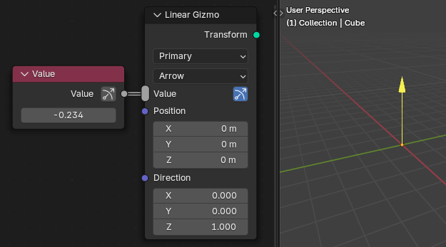
The simplest custom gizmo setup.
When the gizmo position is made dependent on the value, the gizmo works more than one would expect. It now also works in both directions: changing the value moves the gizmo and moving the gizmo changes the value.
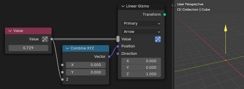
Simple gizmo setup where the gizmo position depends on the controlled value.
Multiple values can be plugged into the Value input of gizmo nodes at once. In that case, all these values are modified at the same time when moving the gizmo. Multiply or divide nodes can be used if the values should change at different rates.
The Transform output of gizmo nodes should be joined into the geometry that the gizmo controls. This helps Blender to understand that the gizmos should be transformed together with the geometry later on.
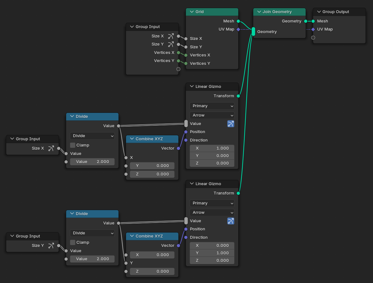
Example showing how to add simple gizmos to the built-in Grid node.
참고
Generally, it is possible to build the entire node group functionality first and to add gizmos afterwards.