UV Operators
Blender offers several ways of mapping UVs, going from simple ones that merely project the mesh’s vertices onto a plane to more advanced ones.
Unwrap
Reference
- Editor:
3D Viewport
- Mode:
Edit Mode
- Menu:
- 단축키(hotkey):
U
Reference
- Editor:
UV Editor
- Mode:
Edit Mode
- Menu:
- 단축키(hotkey):
U
Cuts the selected faces along their seams, flattens them, and lays them out on the UV map. Previously existing UV coordinates are overwritten. Useful for organic shapes.
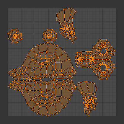
Result of unwrapping Suzanne.
Options
The Adjust Last Operation panel allows fine control over how the mesh is unwrapped:
- Method
- Angle Based:
Uses Angle Based Flattening (ABF). This method gives a good 2D representation of a mesh.
- Conformal:
Uses Least Squares Conformal Mapping (LSCM). This usually results in a less accurate UV mapping than Angle Based, but performs better on simpler objects.
- Minimum Stretch:
Uses Scalable Locally Injective Mapping (SLIM). This tries to minimize distortion for both areas and angles.
- Fill Holes
Virtually fill holes in the mesh before unwrapping, to better avoid overlaps and preserve symmetry.
- Use Subdivision Surface
Use the new vertex positions that were calculated by the Subdivision Surface Modifier (rather than the original positions from before any modifiers are run).
- Original Bounds
Unwrap islands into their original bounds instead of re-packing.
- Correct Aspect
Adjusts the UV mapping to account for the aspect ratio of the image associated with the material. This ensures that UVs are scaled correctly when unwrapping onto non-square textures.
For this option to work, the mesh must have a material with an Image Texture node, and this node must be selected in the Shader Editor.
- Iterations Minimum Stretch
Number of iterations for the Minimum Stretch method, where each iteration reduces the distortion further.
- No Flip Minimum Stretch
Disallow flipping faces. Allowing it sometimes results in less distortion when there are pins.
- Importance Weights Minimum Stretch
Lets you specify a vertex group to manually influence the size of certain faces in the UV map. Faces around high-weight vertices will take up more space in the UV map than ones around low-weight vertices.
When enabling this option, two more appear:
- Weight Group
The name of the vertex group to use.
- Weight Factor
A global factor to multiply all the weights by. A bigger number will result in a more exaggerated difference between high-weight and low-weight areas.
- Margin Method
The meaning of the Margin parameter, which determines the size of the empty space between UV islands.
- Scaled
The Margin is a more or less arbitrary measure with no direct relation to the sizes of the UV islands or the texture.
- Add
As above, but without the internally calculated scaling factor.
- Fraction
The Margin is a fraction of the UV bounds. This means that, if you have a 1024x1024 texture and set the Margin to 1/1024, each UV island will have a margin of 1 pixel around it (and islands will be no closer than 2 pixels to each other).
- Margin
How much empty space to leave between islands. Controlled by Margin Method.
Smart UV Project
Reference
- Editor:
3D Viewport, UV Editor
- Mode:
Edit Mode
- Menu:
- 단축키(hotkey):
U
Examines the angles between the selected faces, cuts them along any sharp edges, then projects each separated group of faces along its average normal and lays it out on the UV map. You can also set up seams for additional cutting. This is a good method for, say, mechanical objects or architecture.
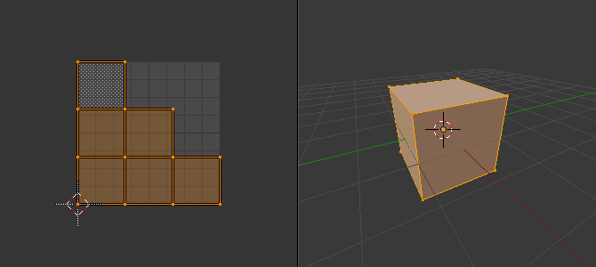
Smart UV project on a truncated pyramid.
Options
The Adjust Last Operation panel allows fine control over how the mesh is unwrapped:
- Angle Limit
The maximum allowed angle between the normals of adjacent faces before they’re split off from each other. A low limit will create lots of small UV islands with little distortion, while a high limit will create a few large islands with potentially more distortion.
- Margin Method
The meaning of the Island Margin parameter, which determines the size of the empty space between UV islands.
- Scaled
The Island Margin is a more or less arbitrary measure with no direct relation to the sizes of the UV islands or the texture.
- Add
As above, but without the internally calculated scaling factor.
- Fraction
The Island Margin is a fraction of the UV unit square. This means that, if you have a 1024x1024 texture and set the Island Margin to 1/1024, each UV island will have a margin of 1 pixel around it (and islands will be no closer than 2 pixels to each other).
- Rotation Method
- Axis-aligned
Automatically rotate to avoid wasting space.
- Axis-aligned (Horizontal)
Rotate islands to be aligned horizontally.
- Axis-aligned (Vertical)
Rotate islands to be aligned vertically.
- Island Margin
How much empty space to leave between islands. Controlled by Margin Method.
- Area Weight
With a value of 0, the projection vector of each face group is simply the average of its face normals. With a value of 1, it’s an average that’s weighted using the faces’ areas. Other values blend between the two.
- Correct Aspect
Adjusts the UV mapping to account for the aspect ratio of the image associated with the material. This ensures that UVs are scaled correctly when unwrapping onto non-square textures.
For this option to work, the mesh must have a material with an Image Texture node, and this node must be selected in the Shader Editor.
- Scale to Bounds
Stretches the resulting UV map to fill the complete texture.
Lightmap Pack
Reference
- Editor:
3D Viewport, UV Editor
- Mode:
Edit Mode
- Menu:
- 단축키(hotkey):
U
Places each selected face separately on the UV map. Lightmaps are commonly used for baking lighting information into a texture for use in realtime rendering – as such, they prioritize using as much of the texture as possible, typically resulting in a disconnected and distorted UV map that would be unsuitable for manual texturing work.
Options
The Adjust Last Operation panel allows fine control over how the mesh is unwrapped:
- Selection
- Selected Faces
Only unwraps the selected faces.
- All Faces
Unwraps the whole mesh.
- Share Texture Space
You can use Multi-Object Editing to generate UV maps for multiple meshes at the same time. When Share Texture Space is enabled, the UV maps won’t overlap each other, so that you can later use the same lightmap texture for all the meshes.
- New UV Map
Creates a new UV map instead of overwriting the currently selected one. See UV Maps.
- Pack Quality
Higher values result in a UV map that wastes less space (but also takes longer to calculate).
- Margin
How much empty space to leave between the faces in the UV map.
Follow Active Quads
Reference
- Editor:
3D Viewport, UV Editor
- Mode:
Edit Mode
- Menu:
- 단축키(hotkey):
U
Starts from the active quad and recursively attaches its neighboring, selected mesh quads to its pre-existing UV quad. Non-quad faces are ignored.
참고
Because the active quad’s UV layout is left unchanged, you’ll typically want to make sure it has the same shape in the UV map as on the mesh before running this unwrap (e.g. by running another type of unwrap on just that face). Otherwise, the distortion will spread to all the other faces.
참고
The resulting UV map may go out of bounds. You can fix this by manually scaling it down or by using Pack Islands.
Options
The Adjust Last Operation panel allows fine control over how the mesh is unwrapped:
- Edge Length Mode
How to calculate the lengths of the UV edges for the newly attached quads.
- Even
Give each new UV edge the same length as the UV edge it’s extending, regardless of its length on the mesh.
- Length
Give each new UV edge a length that’s proportional to its length on the mesh.
- Length Average
Give each new UV edge a length that’s proportional to the average edge length in its edge ring on the mesh.
Cube Projection
Reference
- Editor:
3D Viewport, UV Editor
- Mode:
Edit Mode
- Menu:
- 단축키(hotkey):
U
Projects each selected face onto the most suitable side of a virtual cube, then places all these sides in the UV map, overlapping each other. If you don’t want them to overlap, you can use Pack Islands.
The cube is centered on the Transform Pivot Point and aligned to the mesh’s local axes.
Options
The Adjust Last Operation panel allows fine control over how the mesh is unwrapped:
- Cube Size
The size of the cube to project onto.
- Correct Aspect
Adjusts the UV mapping to account for the aspect ratio of the image associated with the material. This ensures that UVs are scaled correctly when unwrapping onto non-square textures.
For this option to work, the mesh must have a material with an Image Texture node, and this node must be selected in the Shader Editor.
- Clip to Bounds
Moves any out-of-bounds UVs to the nearest border.
- Scale to Bounds
Stretches the resulting UV map to fill the complete texture.
Cylinder Projection
Reference
- Editor:
3D Viewport, UV Editor
- Mode:
Edit Mode
- Menu:
- 단축키(hotkey):
U
Projects the selected faces onto a virtual cylinder, then unrolls that cylinder. The cylinder is centered on the Transform Pivot Point, which is normally the averaged-out position of the selected faces; however, you can also move it to a different place using e.g. the 3D Cursor.
Options
The Adjust Last Operation panel allows fine control over how the mesh is unwrapped:
- Direction, Align
The direction of the cylinder’s central axis.
- View on Equator
Use an axis that’s perpendicular to the viewing direction in the 3D Viewport. If Align is Polar ZX, use the vertical axis of the viewing plane; if it’s Polar ZY, use the horizontal one.
- View on Poles
Use an axis that’s parallel to the viewing direction in the 3D Viewport. Depending on Align, the cylinder will be rotated by 90° around its axis and the UV map will be shifted horizontally by a quarter.
- Align to Object
Use the object’s local Z axis. Depending on Align, the cylinder will be rotated by 90° around its axis and the UV map will be shifted horizontally by a quarter.
- Pole
How to handle vertices that lie on the cylinder’s central axis.
- Pinch
Place all UV versions of the vertex at the same U coordinate. This tends to result in heavily distorted UV faces.
- Fan
Place each UV version of the vertex at a U coordinate that minimizes distortion.
- Preserve Seams
Cut the mesh along its seams before projecting.
- Radius
Half the height of the cylinder (i.e. not its radius; we’re only using the cylinder for projection, so its radius doesn’t matter).
- Correct Aspect
Adjusts the UV mapping to account for the aspect ratio of the image associated with the material. This ensures that UVs are scaled correctly when unwrapping onto non-square textures.
For this option to work, the mesh must have a material with an Image Texture node, and this node must be selected in the Shader Editor.
- Clip to Bounds
Moves any out-of-bounds UVs to the nearest border.
- Scale to Bounds
Stretches the resulting UV map to fill the complete texture.
Sphere Projection
Reference
- Editor:
3D Viewport, UV Editor
- Mode:
Edit Mode
- Menu:
- 단축키(hotkey):
U
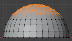
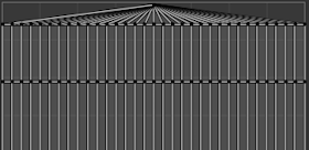
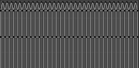
Projects the selected faces onto a virtual sphere, then flattens that sphere much like a world map: the latitude lines vertical and the longitude lines evenly spaced. This is useful for texturing spherical shapes such as eyes or planets.
The sphere is centered on the Transform Pivot Point, which is normally the averaged-out position of the selected faces; however, you can also move it to a different place using e.g. the 3D Cursor.
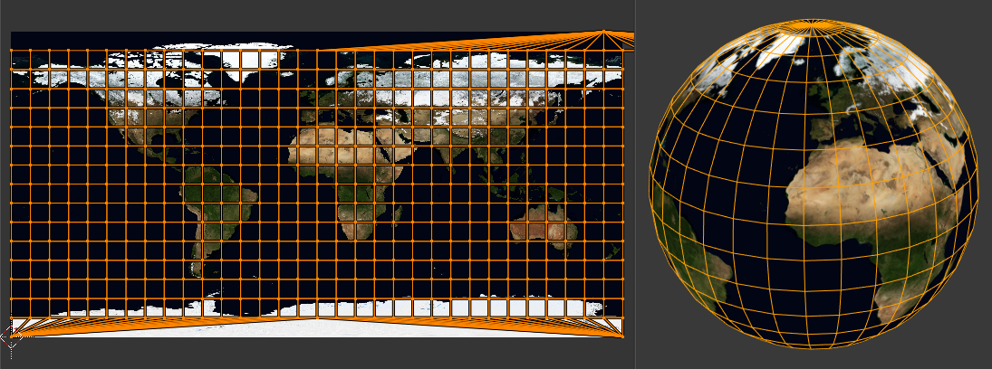
Using an equirectangular image with a Sphere Projection.
Options
The Adjust Last Operation panel allows fine control over how the mesh is unwrapped:
- Direction, Align
The direction of the sphere’s vertical axis.
- View on Equator
Use an axis that’s perpendicular to the viewing direction in the 3D Viewport. If Align is Polar ZX, use the vertical axis of the viewing plane; if it’s Polar ZY, use the horizontal one.
- View on Poles
Use an axis that’s parallel to the viewing direction in the 3D Viewport. Depending on Align, the sphere will be rotated by 90° around its vertical axis and the UV map will be shifted horizontally by a quarter.
- Align to Object
Use the object’s local Z axis. Depending on Align, the sphere will be rotated by 90° around its vertical axis and the UV map will be shifted horizontally by a quarter.
- Pole
How to handle vertices that lie on the sphere’s vertical axis. (See Cylinder Projection for an example.)
- Pinch
Place all UV versions of the vertex at the same U coordinate. This tends to result in heavily distorted UV faces.
- Fan
Place each UV version of the vertex at a U coordinate that minimizes distortion.
- Preserve Seams
Cut the mesh along its seams before projecting.
- Correct Aspect
Adjusts the UV mapping to account for the aspect ratio of the image associated with the material. This ensures that UVs are scaled correctly when unwrapping onto non-square textures.
For this option to work, the mesh must have a material with an Image Texture node, and this node must be selected in the Shader Editor.
- Clip to Bounds
Moves any out-of-bounds UVs to the nearest border.
- Scale to Bounds
Stretches the resulting UV map to fill the complete texture.
Project from View
Reference
- Editor:
3D Viewport
- Mode:
Edit Mode
- Menu:
- 단축키(hotkey):
U
Projects the selected faces onto the view plane. The UV map essentially becomes a wireframe picture of the mesh, taken in the 3D Viewport at the current viewing angle. Use this option if you are using a picture of a real object as a texture. You will get stretching in areas where the model recedes away from you.
Options
The Adjust Last Operation panel allows fine control over how the mesh is unwrapped:
- Orthographic
Use an Orthographic projection instead of Perspective.
- Camera Bounds
Map the borders of the image that would be rendered through the current camera to the borders of the UV map. This option only has an effect when viewing the scene through the camera; see Viewing the Active Camera.
- Correct Aspect
Adjusts the UV mapping to account for the aspect ratio of the image associated with the material. This ensures that UVs are scaled correctly when unwrapping onto non-square textures.
For this option to work, the mesh must have a material with an Image Texture node, and this node must be selected in the Shader Editor.
- Clip to Bounds
Moves any out-of-bounds UVs to the nearest border.
- Scale to Bounds
Stretches the resulting UV map to fill the complete texture.
Project from View (Bounds)
Reference
- Editor:
3D Viewport
- Mode:
Edit Mode
- Menu:
- 단축키(hotkey):
U
The same as Project from View, but with Scale to Bounds activated by default.
Reset
Reference
- Editor:
3D Viewport, UV Editor
- Mode:
Edit Mode
- Menu:
- 단축키(hotkey):
U
Resets the UV layout of each selected face to fill the whole UV area.