Gabor Texture Node
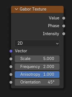
The Gabor Texture node evaluates a Gabor noise at the input texture coordinates. Gabor noise is visually characterized by random interleaved bands whose direction and width can be controlled. Additionally, it can be used to create omnidirectional noise like the standard Noise Texture node, but since it is more expensive to compute, using the Noise Texture node is probably the better option in those cases. See the examples for more information.
Inputs – Уводи
- Vector – Вектор
The coordinates at which Gabor noise will be evaluated. The Z component is ignored in the 2D case. Defaults to Generated texture coordinates if the socket is left unconnected.
- Scale – Масштаб
Scale of the Gabor noise.
- Frequency – Частотність
The rate at which the Gabor noise changes across space. This is different from the Scale input in that it only scales perpendicular to the Gabor noise direction.
- Anisotropy – Анізотропія
The directionality of Gabor noise. 1 means the noise is completely directional, while 0 means the noise is omnidirectional.
- Orientation – Орієнтація
The direction of anisotropic Gabor noise. This is an angle for the 2D case, while it is a unit direction vector for the 3D case.
Properties – Властивості
- Type – Тип
Type of Gabor noise texture.
- 2D:
Evaluates the noise in 2D space. The Z component of the input vector is ignored.
- 3D:
Evaluates the noise in 3D space.
Примітка
Вищі розмірності відповідають більшому часу рендерення, тому нижчі розмірності повинні використовуватися, допоки вищі розмірності не будуть необхідні.
Outputs – Виводи
- Value – Значення
The Gabor noise value with both random intensity and phase. This is equal to sine the phase multiplied by the intensity.
- Phase – Фаза
The phase of the Gabor noise, which has no random intensity.
- Intensity – Інтенсивність
The intensity of the Gabor noise, which has no random phase.
Examples – Приклади
The following table demonstrates different outputs of the node with different parameters. As can be seen, the noise is visually characterized by interleaved bands that are generally oriented in a specific direction. But the Anisotropy parameter can be decreased below 1 to make the bands more random in directions. The Frequency parameter determines the number of bands perpendicular to the direction of the noise. However, the Scale parameter can also be used to globally increase the number of bands, so consider increasing the scale first since high frequency noise can suffer from low contrast and limited interleaving of bands.
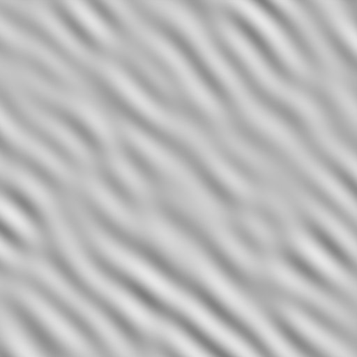
Value output. Frequency = 2. Anisotropy = 1.¶ |
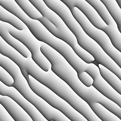
Phase output. Frequency = 2. Anisotropy = 1.¶ |
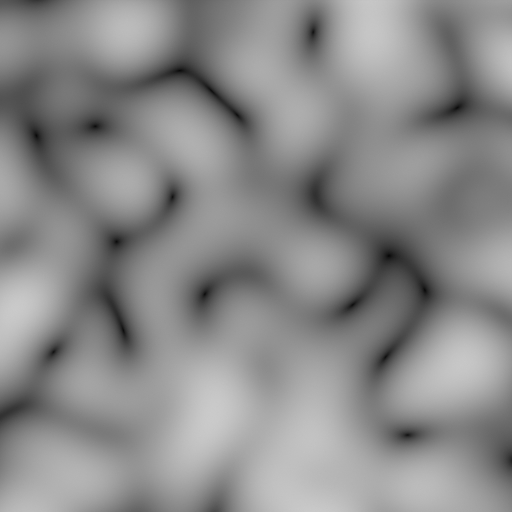
Intensity output. Frequency = 2. Anisotropy = 1.¶ |
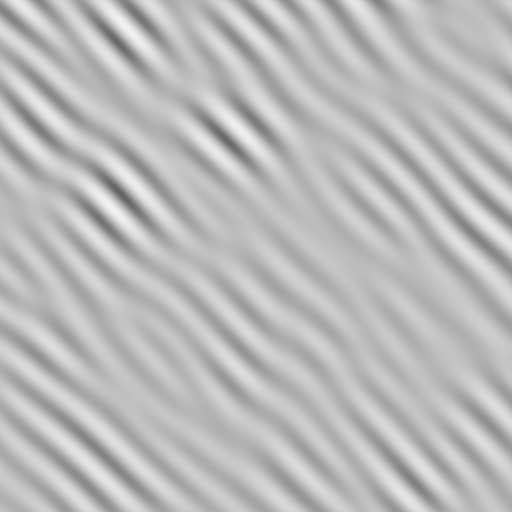
Value output. Frequency = 3. Anisotropy = 1.¶ |
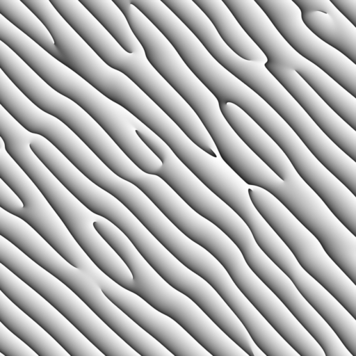
Phase output. Frequency = 3. Anisotropy = 1.¶ |
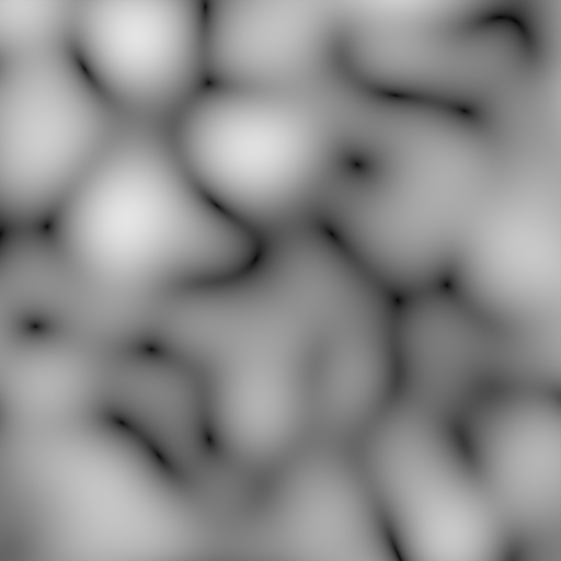
Intensity output. Frequency = 3. Anisotropy = 1.¶ |
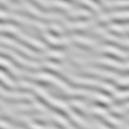
Value output. Frequency = 2. Anisotropy = 0.7.¶ |
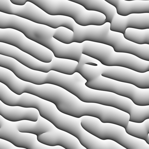
Phase output. Frequency = 2. Anisotropy = 0.7.¶ |
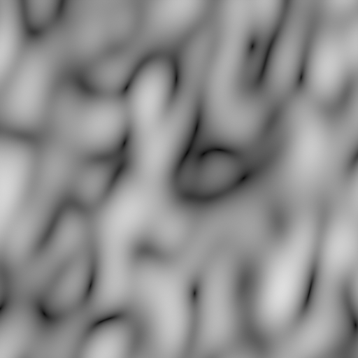
Intensity output. Frequency = 2. Anisotropy = 0.7.¶ |
Gabor noise is decomposed into a Phase and an Intensity components, where the Gabor value is computed as sine the phase multiplied by the intensity, noting that the phase output is normalized to the [0, 1] range.
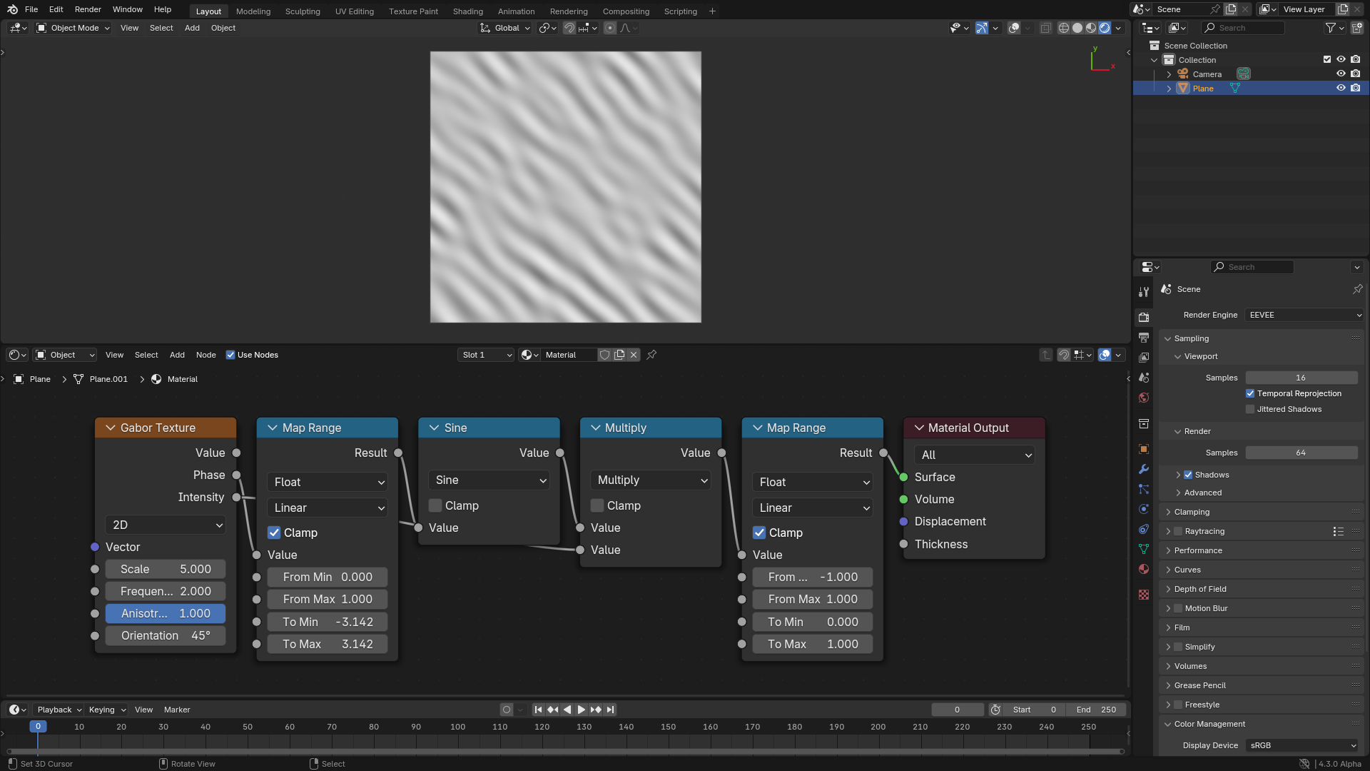
Compute the value output from the phase and intensity outputs.
The advantage of the Phase output is that it has no random intensities and no low contrast areas as in the value output, so it can be used as a base for textures that are more structured in nature, like sand dunes.
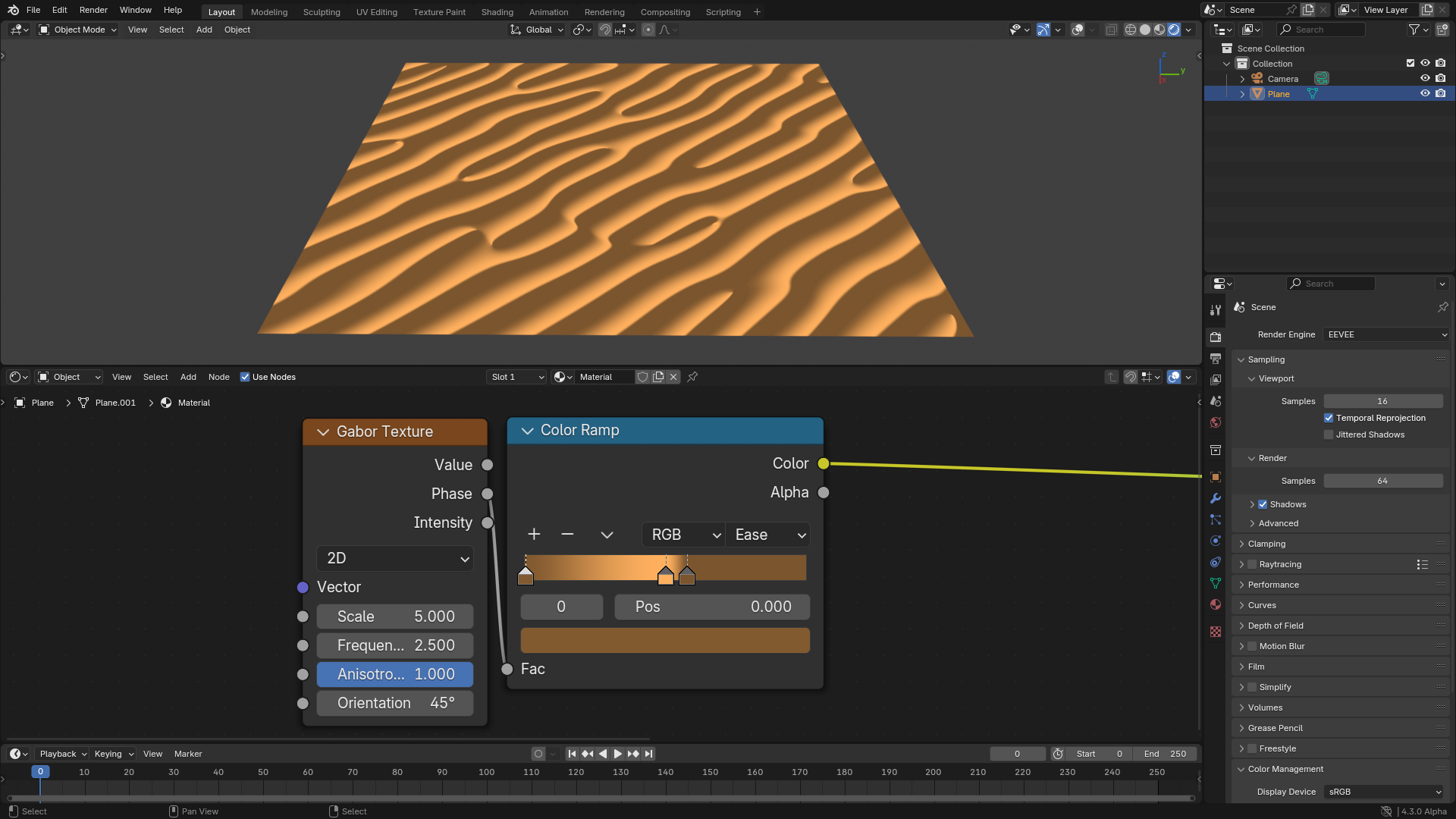
Sand dune-like structures creates using the phase output.
The main advantage and use of the Intensity output is that it provides information about the location of singularities in the Phase output. Singularities are those areas in the phase where the bands meet, which are shown in red in the following figure. Those areas will be close to zero in the Intensity output. So if those areas are undesirable, they can be hidden by multiplying by a variant of the Intensity output.
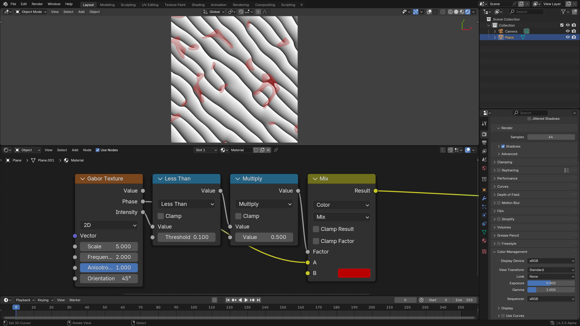
Visualization of the areas where singularities happen.
Inputs can be varies across space to get more interesting patterns.
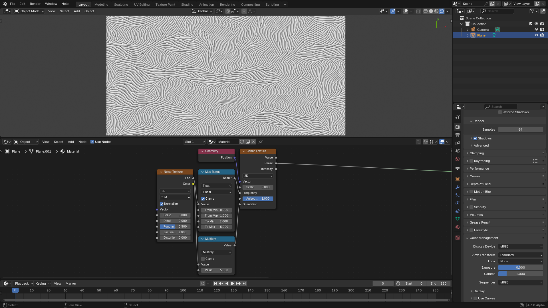
Varying the frequency and orientation across space.