Transfer Mesh Data
Reference (Referentie)
- Mode (Modus):
Object Mode (Objectmodus)
- Menu:
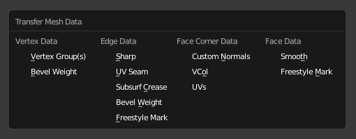
Transfer Mesh Data copies a certain type of data from the active mesh to the selected meshes. This could be UV maps, color attributes, custom normals, and so on.
For each element (vertex/edge/face) in each destination mesh, the operator finds one or more matching elements in the source mesh, then interpolates between those source elements’ values.
Zie ook
The Adjust Last Operation (Laatste operatie aanpassen) panel offers the following options.
- Freeze Operator
Prevent changes to the settings from re-running the data transfer. This is useful if you are editing several settings at once with heavy geometry.
- Data Type
Which data to transfer.
Data types.
- Create Data
Add any missing data layers on the destination meshes (e.g. create missing vertex groups).
- Mapping
Hoe het (de) overeenkomende bronelement(en) te vinden voor elk bestemmingselement. De verschillende opties worden uitgelegd in het gedeelte Mapping hieronder.
- Auto Transform
If the source and destination meshes don’t overlap in world space, you can enable this option to calculate a transformation automatically. While this is quick and easy, however, you may get better results by making them overlap by hand.
- Object Transform
Whether take into account the world space transformations of the source and destination objects. When unchecked, the operator acts like all objects are in the same position and have the default rotation and scale.
- Only Neighbor Geometry
Only consider source elements that are close enough to the destination one.
- Max Distance
Maximum allowed distance between source and destination element (for non-topology mappings).
- Ray Radius
The starting radius to use when ray casting.
For certain mapping types, the operator performs a series of ray casts from each destination element to find matching source elements. These ray casts start with the specified radius and grow progressively larger until a match is found or a limit is reached.
A low starting radius will give more accurate results, but has worse performance if it’s too small and needs to be increased. A high starting radius has better performance, but may result in suboptimal matches.
In general, use a low radius for dense source meshes and a high one for simple ones.
- Islands Precision
Regelt de berekening die voorkomt dat een bestemmingsvlak UV-coördinaten ontvangt van ongelijksoortige bron UV-eilanden (gebieden begrensd door :doc: seams </modeling/meshes/uv/unwrapping/seams>). Dit op 0,0 houden betekent helemaal geen eiland berekening, terwijl hogere getallen de correctheid van het resultaat verhogen ten koste van extra rekenwerk.
Over het algemeen zijn kleine waarden zoals 0,02 genoeg om goede resultaten te krijgen, maar als men een zeer hoogpolige bron in kaart brengt naar een zeer laagpolige bestemming, moet je de waarde misschien aanzienlijk verhogen.
- Source Layers Selection
Which source layers to copy to the destination meshes (e.g. only the active vertex group, all vertex groups, or a specific vertex group).
- Destination Layers Matching
Hoe vind men de bestemmingslaag voor een bepaalde bronlaag: op naam of op volgorde.
- Mix Mode
How to combine the new data from the source mesh with the original data in the destination meshes.
- Replace (Vervangen)
Interpoleer tussen de originele en nieuwe waarde met behulp van Mix Factor.
- Above Threshold (Bovendrempelwaarde)
Vervang de bestemmingswaarde als deze groter of gelijk is aan Mix Factor. In het geval van data met meerdere componenten, zoals kleuren, wordt de drempelwaarde vergeleken met het gemiddelde van deze componenten.
For boolean Data Types like Freestyle Mark, you can use this to perform a logical AND: simply ensure the Mix Factor is 0.5 or greater, and the destination mesh will only have marked edges/faces that were already marked and are also marked in the source mesh.
- Below Threshold (Onderdrempelwaarde)
Vervang de bestemmingswaarde als deze kleiner of gelijk is aan Mix Factor. In het geval van data met meerdere componenten, zoals kleuren, wordt de drempelwaarde vergeleken met het gemiddelde van deze componenten.
For boolean Data Types like Freestyle Mark, you can use this to perform a logical OR: simply ensure the Mix Factor is 0.5 or greater, and the destination mesh will have marked edges/faces that were already marked or are marked in the source mesh.
- Mix (Mixen)
Meng de bronwaarde met de bestemmingswaarde, bijvoorbeeld door een alfa-blend uit te voeren in het geval van kleurattributen. Interpoleer vervolgens met behulp van Mix Factor.
- Add (Toevoegen)
Tel de bronwaarde op bij de bestemmingswaarde en interpoleer dan met Mix Factor.
- Subtract (Aftrekken)
Trek de bronwaarde af van de bestemmingswaarde en interpoleer dan met Mix Factor.
- Multiply (Vermenigvuldigen)
Vermenigvuldig de bronwaarde met de bestemmingswaarde en interpoleer dan met Mix Factor.
- Mix Factor
Interpolatiefactor tussen de oorspronkelijke bestemmingswaarde en de nieuw berekende waarde. Als Mix Mode Above Threshold of Below Threshold is, is dit een drempelwaarde.
Mapping
Topology (Topologie)
Simply matches the elements based on their index. This requires all meshes to have the same number of elements and those elements to be ordered in the same way. Best suited for a destination mesh that’s a deformed copy of the source.
Zie ook
Sort Elements (Sorteer Elementen) to ensure the objects have the same element ordering.
One-To-One Mappings
Deze toewijzingen selecteren altijd slechts één bronelement voor elk bestemmingselement.
- Vertex Data (Hoekpuntdata)
- Nearest Vertex
Gebruik het dichtstbijzijnde bronpunt.
- Nearest Edge Vertex (Dichtstbijzijnde hoekpunt)
Gebruik het dichtstbijzijnde bronpunt op de dichtstbijzijnde (op middelpuntsafstand) bronrand.
- Nearest Face Vertex (Dichtstbijzijnd Vlak Hoekpunt)
Gebruik het dichtstbijzijnde bronpunt op het dichtstbijzijnde (door middelpuntafstand) bronvlak.
- Edge Data (Randdata)
- Nearest Vertices (Dichtstbijzijnde Punten)
Gebruik de bronrand waarvan de hoekpunten het dichtst bij die van de bestemmingsrand liggen.
- Nearest Edge (Dichtstbijzijnde Rand)
Gebruik de bronrand waarvan het middelpunt het dichtst bij dat van de bestemmingsrand ligt.
- Nearest Face Edge (Dichtstbijzijnde Vlakrand)
Gebruik de dichtstbijzijnde bronrand op het dichtstbijzijnde vlak (beide door middelpuntafstand).
- Face Corner Data (Vlakhoekdata)
Een Vlakhoek is een vertex (punt) in de context van een vlak. Dit concept wordt het meest gebruikt in UV-maps: elke vlakhoek kan zijn eigen UV-coördinaat hebben, of met andere woorden, één 3D vertex (punt) kan overeenkomen met meerdere UV punten (één per vlak).
- Nearest Corner and Best Matching Normal (Dichtstbijzijnde Hoek en Best Passende Normaal)
Gebruik de bronhoek die het dichtst bij de bestemmingshoek ligt en de meest gelijkende deelnormaal heeft.
- Nearest Corner and Best Matching Face Normal (Dichtstbijzijnde Hoek en Best Overeenkomende Vlaknormaal)
Gebruik de bronhoek die het dichtst bij de doelhoek ligt en de meest gelijkende vlaknormaal heeft.
- Nearest Corner of Nearest Face
Use the nearest source corner on the nearest source face.
- Face Data (Vlakdata)
- Nearest Face
Use the nearest source face (by midpoint distance).
- Best Normal-Matching
Cast a ray from the destination face’s centerpoint along the face’s normal and use the source face found this way.
Interpolated Mappings
These mappings can match several source elements and interpolate between their values.
- Vertex Data (Hoekpuntdata)
- Nearest Edge Interpolated
Find the nearest point on the nearest source edge, then use that point to interpolate between the values of the edge’s vertices.
- Nearest Face Interpolated
Find the nearest point on the nearest source face, then use that point to interpolate between the values of the face’s vertices.
- Projected Face Interpolated
Project the destination vertex along its normal onto a source face, then use the projected point to interpolate between the values of the face’s vertices.
- Edge Data (Randdata)
- Projected Edge Interpolated
Find source edges by projecting from a number of points on the destination edge (where each point is projected along the interpolated normals of the destination edge’s vertices). Then, interpolate between the values of the source edges found this way.
- Face Corner Data (Vlakhoekdata)
- Nearest Face Interpolated
Find the nearest point on the nearest source face, then use that point to interpolate between the values of the face’s corners.
- Projected Face Interpolated
Project the destination corner along its normal onto a source face, then use the projected point to interpolate between the values of the face’s corners.
- Face Data (Vlakdata)
- Projected Face Interpolated
Find source faces by casting rays from a number of points on the destination face along the destination face’s normal. Then, interpolate between the values of these source faces.