Extrude Mesh Node
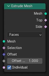
The Extrude Mesh Node generates new edges or faces on the selected geometry elements and moves them by a certain offset.
The operations are similar to the extrude tools in mesh edit mode, though there are some differences. Most importantly, the node never keeps the back-faces of the extrusion in place, they are always removed. Attribute propagation rules may also be different.
入力
- Mesh(メッシュ)
標準のジオメトリ入力です。
- Selection(選択)
A boolean field indicating which elements should be extruded.
- Offset(オフセット)
The translation vector for each extruded element. By default, this is the element's normal.
Tip
If all the elements are extruded in the same direction, you may be able to improve performance by connecting a Vector(ベクトル)ノード to this input, thereby skipping the normal calculation.
- Offset Scale
Scaling factor for the above translation vector.
- Individual Face Mode Only
Whether to extrude each face individually rather than extruding connected groups of faces together.
Properties(プロパティ)
- Mode(モード)
- Vertices(頂点):
Attaches a new freestanding edge to each selected vertex.
- Edges(辺):
Attaches a new quad face to each selected edges. Vertices shared by the original selected edges are also shared in the duplicated edges.
注釈
Depending on the situation, the normals of the new faces may be arbitrary. If the selected edges each have only one connected face, then the node can pick a consistent orientation for the new faces, but if there is more than one connected face, or no connected faces, the normals may have to be adjusted afterwards.
- Faces(面):
Extrudes contiguous regions of selected faces, or each selected face individually, depending on the Individual boolean input.
When the Individual input is false, the node will find regions of connected faces and generate new "side" faces on the boundaries of those regions. Any vertices, edges or faces on the inside of the regions simply are moved, not duplicated. If the whole mesh is selected and it is already a Manifold shape, then the result will just be that the whole mesh gets resized.
Output(出力)
- Mesh(メッシュ)
標準のジオメトリ出力です。
- Top(上)
A boolean field indicating the "top" elements in the extrusion. In Vertex mode, these are the new vertices; in Edge mode, the new edges; and in Face mode, the moved faces.
- Side(サイド)
A boolean field indicating the "side" elements in the extrusion. In Vertex mode, these are the new edges; in Edge mode, the new faces; and in Face mode, too, the newly generated faces (as opposed to the moved ones).
例
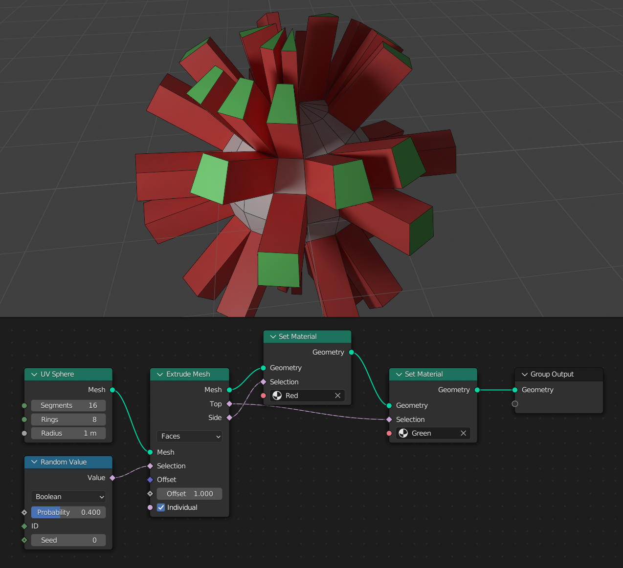
Here, the selection outputs are used to set materials on certain faces of the mesh. A Random Value Node is used to limit the extrusion to a random set of faces.
Attribute Propagation
Attributes are transferred to the new elements with specific rules.
An attribute will never change domains on the resulting mesh.
The id attribute does not have any special handling.
Generally boolean attributes are propagated with "or", meaning any connected "true" value that is mixed in for other types will cause the new value to be "true" as well.
The following sections describe:
Vertex Mode
The new edges created in vertex mode use the average value of all connected edges.
New vertices have copied values from their original vertices.
New edges have the average value of any connected original edges. For boolean attributes, edges are selected if any connected edges were selected.
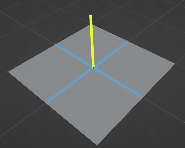
Edge Mode
Attribute propagation for new connecting edges (the vertical yellow edge). The final value is a mix of the values from the two middle blue edges. The darker maroon edges lower on the image are not used.
New vertices have copied values from their original vertices.
Vertical connecting edges get the average value from any connected extruded edges. For booleans, the edges are selected if any connected extruded edges were selected. (Propagation rules are shown in the figure above.)
Horizontal duplicate edges have copied values from their original edges.
New faces get the average values of all faces connected to the selected edge. For booleans, faces are selected if any connected original faces were selected.
New face corners get the averaged value of corresponding corners in all faces connected to selected edges. For booleans, corners are selected if one of those corners are selected.
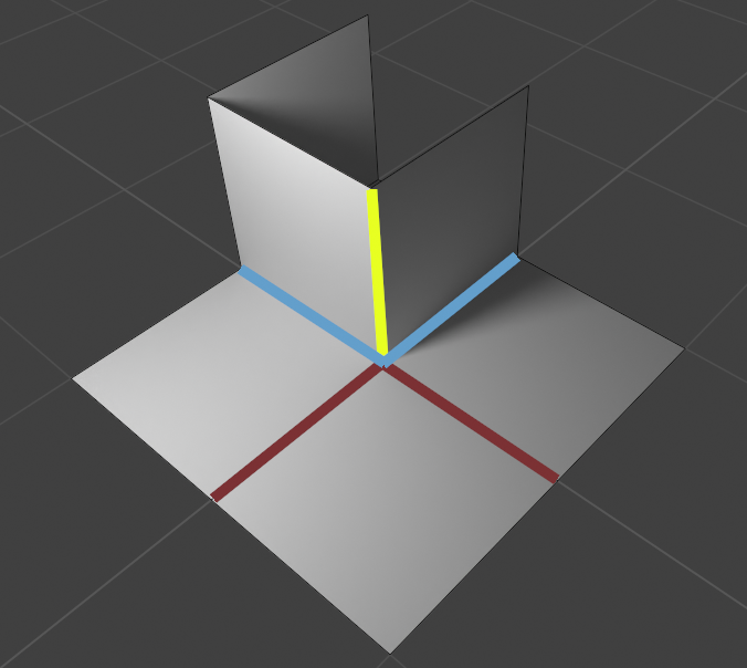
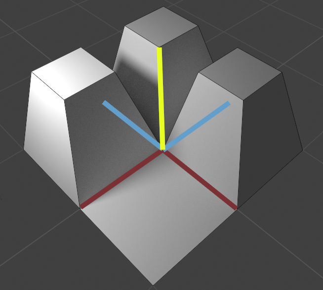
Face Mode

Attribute propagation for new connecting edges (the vertical yellow edge). The final value is a mix of the values from the two middle blue edges. The values from the darker maroon edges between unselected faces and on top of the extruded region are not used.
New vertices have copied values from their original vertices.
Vertical connecting edges get the average value from any connected extruded edges, not including the edges "on top" of extruded regions. For booleans, the edges are selected if any of those connected edges were selected. (Propagation rules are shown in the figure above.)
Horizontal duplicate edges have copied values from their original edges.
New faces have copied values from the corresponding extruded faces.
New face corners have copied values from the corresponding corresponding corners of extruded faces.
Individual Face Mode
Attribute propagation for new connecting edge. Each edge uses the average values of the two neighboring edges on its extruded face.
New vertices have copied values from their original vertices.
Vertical connecting edges get the average value of the two neighboring edges on each extruded face. For booleans, the edges are selected when at least one neighbor on the extruded face was selected.
Horizontal duplicate edges have copied values from their original edges.
New side faces have copied values from their corresponding selected face.
New face corners have copied values from the corresponding corners of selected faces.