Đinh Vít (Screw)
Tham Chiếu [Reference]
- Chế Độ [Mode]:
Chế Độ Biên Soạn [Edit Mode]
- Trình Đơn [Menu]:
The Screw operator extrudes geometry along a helix. You can use it to create screws, springs, sea shells and so on.
Trong khi it's tương tự tới the Bộ Điều Chỉnh Xoáy Ốc (Screw Modifier), có some quan trọng differences:
Đinh Vít thao tác |
Bộ điều chỉnh xoáy ốc [Screw modifier] |
|---|---|
Làm Việc không gian thế giới |
Làm Việc không gian đối tượng |
Đẩy Trồi duy the đã chọn hình học. |
Đẩy Trồi hình học |
The centerpoint can be specified manually. |
The centerpoint is always the object's origin. |
Cái/Số Một revolution được luôn luôn 360°. |
The góc độ có thể be đã chọn freely. |
The chiều cao dịch chuyển của mỗi một revolution được tính toán tự động dựa trên the hình học. |
The height offset must be specified manually. |
Each revolution can also have a radial offset away from/towards the central axis (again determined by the geometry). |
The bán kính stays hằng số/đồng đều/bất biến. |
As described above, the Screw operator automatically determines the height offset and radial offset to apply after each revolution. It does this by looking for the endpoints of an open profile -- a series of connected edges that don't form a closed loop. The geometry is extruded so that the profile's top vertex in one revolution will coincide with the bottom vertex in the next.
The most common use case is extruding such an open profile. You're not limited to this, however. As long as there is one open profile in the selection -- even just a single loose edge -- you can also extrude closed profiles and even geometry with faces.
You can see some examples below.
Cách Dùng [Usage]
First, make sure you have an open profile in your mesh. If you want to extrude anything else (such as one or more circles), you should create an open profile next to it.
Once that's done, enter Edit Mode and select the geometry you want to extrude, making sure to include exactly one open profile. If you have fewer or more, the operator will fail with the error "You have to select a string of connected vertices too."
Make sure the Con Trỏ 3D (3D Cursor) is at the centerpoint around which you want the geometry to turn. Also make sure that the vertical axis on your screen matches the direction of the axis around which it should turn. The most common example is turning around the global Z axis: for that, you'd place the 3D Cursor at the world origin and switch to an orthographic side view.
Now you're ready to run the operator: open the Edge menu (by clicking it in the 3D Viewport's header or pressing Ctrl-E) and click Screw.
You có thể thay đổi the số/lượng của số phân/bước và số vòng xoay trong Điều Chỉnh Thao Tác Trước Đây (Adjust Last Operation) bảng.
If you only created an open profile to guide the extrusion (not because you wanted its geometry), you can select its extruded faces by hovering over one and pressing L, then delete them by pressing X or Delete.
Các Tùy Chọn (Options)
Đinh Vít bảng (Chế Độ Biên Soạn).
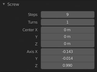
- Số Phân/Bước (Steps)
The số/lượng của extrusions được hoàn thành cho/đối với mỗi một 360° chuyển hướng/rẽ.
- Số Vòng Xoay (Turns)
The số/lượng của số vòng xoay tới kiến tạo.
- Trung Tâm X, Y, Z (Center X, Y, Z)
The world space coordinates of the centerpoint around which to spin the geometry. Initially this is the location of the 3D Cursor.
- Trục X, Y, Z (Axis X, Y, Z)
The direction vector around which to spin the geometry. Initially this is the screen-space vertical axis (so the global Z axis when in a side view or the global Y axis when in top view). By inverting the Axis, you can flip between going clockwise and counterclockwise.
Mẹo
You can use the Align View to Active menu item to align the viewport, and thereby the Axis, to a certain item in the scene.
Notice that the Axis only determines how the geometry spins "horizontally" around the centerpoint. It doesn't determine how the geometry moves "vertically." Instead, the geometry always moves by a distance and direction given by the endpoints of the open profile, and goes downward in the object's local space.
Một Số Ví Dụ (Examples)
Tạo một Đàn Hồi [Creating a Spring]
First, let's create a circle to serve as the spring's cross section:
Mở Blender và xóa khối lập phương Cube mặc định.
Thêm một hình/vòng/tròn bởi/theo pressing Shift-A lựa chọn .
Set the Location X property of this new object to -3 and its Rotation X property to 90°.
Bước vào/Chuyển sang "Chế Độ Biên Soạn" bởi/theo pressing Tab.
Chuyển Mạch tới the "Trực Giao Trước" góc nhìn bởi/theo pressing Số 1 Bàn Số (Numpad1).
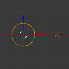
Đẩy Trồi/Kéo ra mặt cắt created.
Next, let's create a vertical line to specify the distance between spring loops:
Deselect all vertices by clicking on an empty space or pressing Alt-A.
Click Ctrl-RMB twice to create two vertices connected by an edge.
Select both vertices and press S X 0 Return to ensure they have the same X coordinate. (This is necessary to keep the spring's radius constant.)
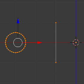
Hướng Dẫn mặt cắt created.
Now, we're ready to create the spring:
Lựa Chọn cả hai the hình/vòng/tròn và the đường nét/thẳng bởi/theo pressing A.
Bấm Chuột .
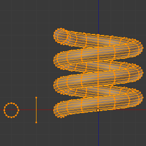
Adjust the Steps and Turns to your liking.
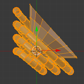
Try changing Axis Z to -1 and see that this makes the spring turn the other way.
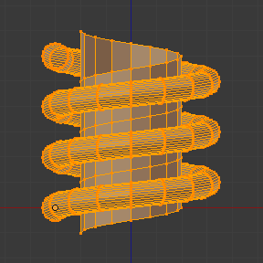
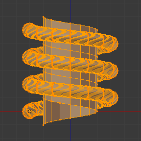
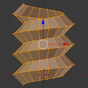
You can get some interesting results by making the Axis diagonal (e.g. keeping Axis Z at -1 and setting Axis X to 1). Notice that each individual spring loop is inclined by 45°, but that after each loop, we still go down vertically (in the direction of the guide line).
|
|
Tạo một Đinh Vít Spindle [Creating a Screw Spindle]
The Screw operator is perfectly suited for creating helices without any gaps between the turns.
Mở Blender bước vào/chuyển sang "Chế Độ Biên Soạn" cho/đối với the mặc định khối lập phương.
Xóa toàn bộ các điểm đỉnh bởi/theo pressing X hoặc Xóa (Delete).
Chuyển Mạch tới the "Trực Giao Trước" góc nhìn bởi/theo pressing Số 1 Bàn Số (Numpad1).
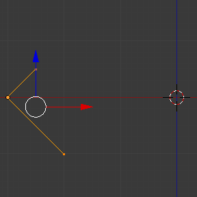
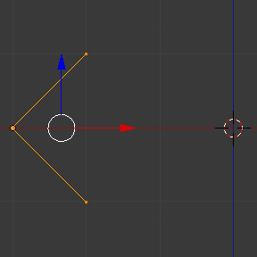
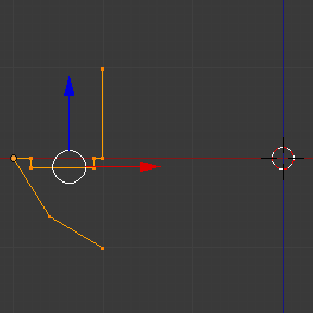
Click Ctrl-RMB three times to create a profile like the one below.
Select the two vertices closest to the global Z axis and press S X 0 Return to ensure they have the same X coordinate.
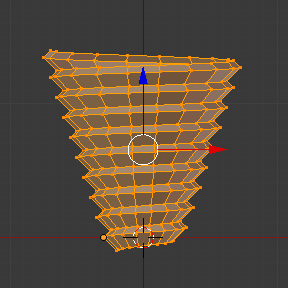
Lựa Chọn toàn bộ ba điểm đỉnh và bấm chuột .
Adjust the Steps and Turns to your liking.
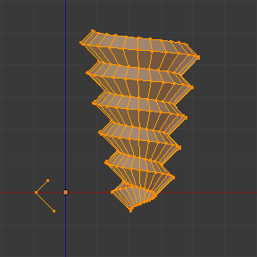
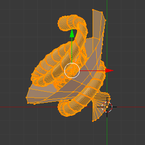
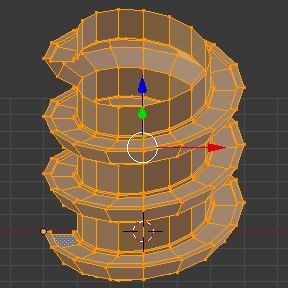
You can also create more interesting shapes, like this spiral "staircase":
Tạo Một cái Đầu Vít [Creating a Screw Tip]
Until now, we've always made sure that the first and last vertex of the profile have the same X coordinate, thereby keeping the radius of the helix constant. However, nothing stops you from using different X coordinates and having the helix shrink/expand along its height.