螺旋
参考
- 模式:
编辑模式
- 菜单:
螺旋 操作可沿着螺旋线挤出几何体。您可以用它来创建螺丝、弹簧、海螺等。
虽然它与螺旋修改器类似,但有一些重要区别:
螺旋操作项 |
螺旋修改器 |
|---|---|
在世界空间工作。 |
在物体空间工作。 |
仅挤出选中的几何。 |
挤出全部几何。 |
中心点可以手动指定。 |
中心点始终是物体原点。 |
一圈总是 360°. |
角度可自由选择。 |
每次旋转的高度偏移会根据几何形状自动计算。 |
高度偏移必须手动指定。 |
每次旋转还可以有一个偏离/朝向中心轴的径向偏移(同样由几何决定)。 |
半径保持不变。 |
如上所述,螺旋操作会自动确定每次旋转后的高度偏移和径向偏移。它是通过寻找开放轮廓的端点来实现的,开放轮廓是指不形成闭合循环的一系列相连边。几何体被挤出后,轮廓的上顶点在一次旋转中将与下一次旋转中的下顶点重合。
最常见的使用情况是挤出这种开放式轮廓。但您并不局限于此。只要选区中有一个开放的轮廓,哪怕只是一条松散的边,也可以挤出封闭的轮廓,甚至挤出具有面的几何体。
您可以查看下面的一些例子。
用法
首先,确保您的网格中有一个开放的轮廓。如果要挤出其他任何东西(如一个或多个圆),则应在其旁边创建一个开放轮廓。
完成后,进入 编辑模式,选择要挤出的几何体,确保包含一个开放的轮廓。如果数量较少或较多,操作会失败,并显示错误 “你还必须另选一串相连的顶点。”
确保 3D 游标 位于您希望几何体围绕其转动的中心点。还要确保屏幕上的垂直轴与几何体绕轴转动的方向一致。最常见的例子是围绕全局 Z 轴旋转:为此,您需要将 3D 游标置于世界原点,然后切换到正交侧视图。
现在您可以运行操作了:打开 边 菜单(在 3D 视口的标题栏中点击该菜单或按 Ctrl-E),然后点击 螺旋。
您可以在调整上一步操作面板中更改步数和圈数。
如果您创建一个开放轮廓只是为了引导挤出(而不是因为需要它的几何形状),您可以将鼠标悬停在一个轮廓上并按 L 键来选择它的挤出面,然后按 X 或 Delete 键删除它们。
选项
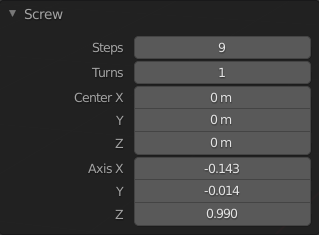
螺旋面板(编辑模式下)。
- 步数 (阶梯)
每转 360° 需要挤出的次数。
- 圈数
要创建的回转数。
- 中心 X, Y, Z
围绕几何体旋转的中心点的世界空间坐标。最初,这是 3D 游标的位置。
- 轴向 X, Y, Z
围绕几何体旋转的方向矢量。最初,它是屏幕空间的垂直轴(因此,在侧视图中是全局 Z 轴,在俯视图中是全局 Y 轴)。通过反转 轴向 可以在顺时针和逆时针之间切换。
Tip
您可以使用视图对齐活动项菜单项对齐视口,从而将 轴向 对齐到场景中的某个项目。
请注意,轴向 只决定几何体如何围绕中心点 “水平” 旋转。它并不决定几何体如何 “垂直” 移动。相反,几何体的移动距离和方向始终由开放轮廓的端点决定,并在物体的局部空间中向下移动。
示例
创建一个弹簧
首先,让我们创建一个圆形作为弹簧的横截面:
打开 Blender,删除默认立方体。
按下 Shift-A 并选择 以创建一个圆环。
设置新建物体的 位置 X 属性为 -3,并设置 旋转 X 属性为 90°.
按下 Tab 进入 编辑模式。
按 数字键盘1 键切换到 正交前视图。
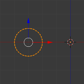
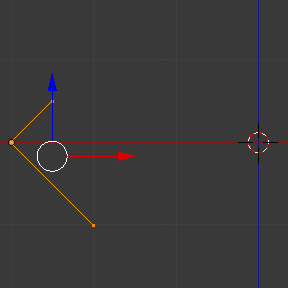
创建了挤出轮廓。
Next, let's create a vertical line to specify the distance between spring loops:
点击空白处或按下 Alt-A 以取消选择全部顶点。
点击 Ctrl-鼠标右键 两次以创建两个以边相连的顶点。
选择两个顶点并按 S X 0 回车 键,确保它们的 X 坐标相同。(这是保持弹簧半径不变所必需的。)
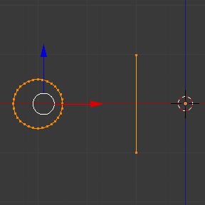
创建了引导轮廓。
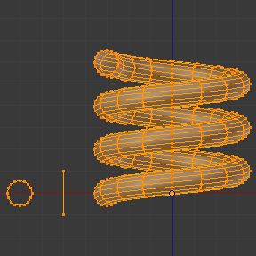
现在,我们准备制作弹簧:
按 A 键同时选择圆环和线段。
点击 。
根据自己的喜好调整 步数 和 圈数。
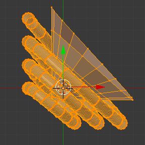
试着将 轴向 Z 改为 -1,看看是否能使弹簧反向旋转。
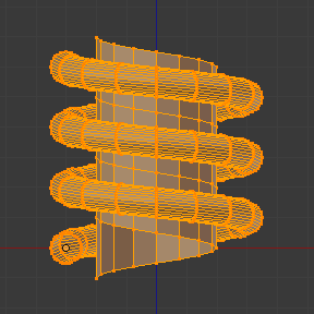
将 轴向 设为对角线(例如,将 轴向 Z 设为 -1,将 轴向 X 设为 1)可以得到一些有趣的结果。请注意,每个弹簧环都倾斜了 45°,但在每个环之后,我们仍然垂直向下(沿着引导线的方向)。
|
|
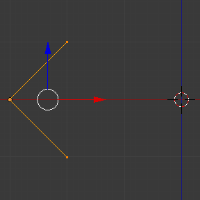
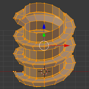
创建一根螺杆
The Screw operator is perfectly suited for creating helices without any gaps between the turns.
打开 Blender 并进入默认立方体的 编辑模式。
按下 X 或 Delete 删除所有顶点。
按 数字键盘1 键切换到 正交前视图。
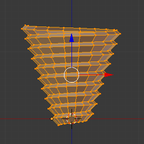
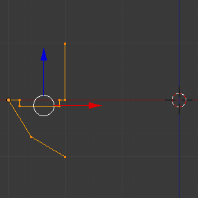
点击 Ctrl-鼠标右键 三次,创建类似下图的轮廓。
选择最靠近全局 Z 轴的两个顶点,然后按 S X 0 回车 键,确保它们具有相同的 X 坐标。
选择所有三个顶点然后点击 。
根据自己的喜好调整 步数 和 圈数。
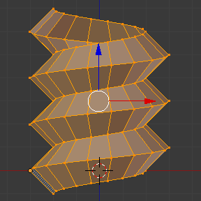
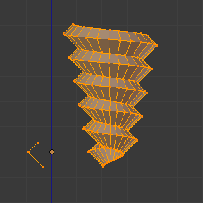
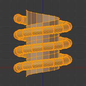
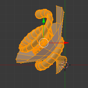
你还可以创造出更有趣的形状,比如这个螺旋形的 “楼梯”:
创建一枚螺钉
到目前为止,我们总是确保剖面的第一个和最后一个顶点具有相同的 X 坐标,从而保持螺旋半径不变。但是,您也可以使用不同的 X 坐标,让螺旋沿高度方向收缩/扩张。