Enroscar
Referencia
- Modo:
Modo Edición
- Menú:
The Screw operator extrudes geometry along a helix. You can use it to create screws, springs, sea shells and so on.
While it’s similar to the Screw Modifier, there are some important differences:
El operador Enroscar |
El modificador Enroscar |
|---|---|
Funciona en espacio global. |
Funciona en espacio del objeto. |
Extruye sólo la geometría seleccionada. |
Extruye toda la geometría. |
El punto central podrá ser especificado manualmente. |
The centerpoint is always the object’s origin. |
Una revolución siempre será de 360°. |
The angle can be chosen freely. |
El desplazamiento en la altura de cada revolución será calculado automáticamente, basado en la geometría. |
The height offset must be specified manually. |
Each revolution can also have a radial offset away from/towards the central axis (again determined by the geometry). |
El radio permanecerá constante. |
As described above, the Screw operator automatically determines the height offset and radial offset to apply after each revolution. It does this by looking for the endpoints of an open profile – a series of connected edges that don’t form a closed loop. The geometry is extruded so that the profile’s top vertex in one revolution will coincide with the bottom vertex in the next.
The most common use case is extruding such an open profile. You’re not limited to this, however. As long as there is one open profile in the selection – even just a single loose edge – you can also extrude closed profiles and even geometry with faces.
Debajo se pueden apreciar varios ejemplos.
Uso
First, make sure you have an open profile in your mesh. If you want to extrude anything else (such as one or more circles), you should create an open profile next to it.
Once that’s done, enter Edit Mode and select the geometry you want to extrude, making sure to include exactly one open profile. If you have fewer or more, the operator will fail with the error «You have to select a string of connected vertices too.»
Make sure the Cursor 3D is at the centerpoint around which you want the geometry to turn. Also make sure that the vertical axis on your screen matches the direction of the axis around which it should turn. The most common example is turning around the global Z axis: for that, you’d place the 3D Cursor at the world origin and switch to an orthographic side view.
Now you’re ready to run the operator: open the Edge menu (by clicking it in the 3D Viewport’s header or pressing Ctrl-E) and click Screw.
Será posible cambiar la cantidad de intervalos y vueltas en el panel Ajustar última operación.
If you only created an open profile to guide the extrusion (not because you wanted its geometry), you can select its extruded faces by hovering over one and pressing L, then delete them by pressing X or Delete.
Opciones
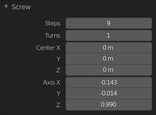
Panel de Enroscar (en modo Edición).
- Intervalos
La cantidad de extrusiones a realizar, por cada revolución de 360°.
- Revoluciones
La cantidad de vueltas a crear.
- Centro X, Y, Z
The world space coordinates of the centerpoint around which to spin the geometry. Initially this is the location of the 3D Cursor.
- Ejes X, Y, Z
The direction vector around which to spin the geometry. Initially this is the screen-space vertical axis (so the global Z axis when in a side view or the global Y axis when in top view). By inverting the Axis, you can flip between going clockwise and counterclockwise.
Truco
You can use the Align View to Active menu item to align the viewport, and thereby the Axis, to a certain item in the scene.
Notice that the Axis only determines how the geometry spins «horizontally» around the centerpoint. It doesn’t determine how the geometry moves «vertically.» Instead, the geometry always moves by a distance and direction given by the endpoints of the open profile, and goes downward in the object’s local space.
Ejemplos
Creación de un muelle
First, let’s create a circle to serve as the spring’s cross section:
Abrir Blender y eliminar el Cubo predefinido.
Agregar un círculo pulsando Mayús-A y seleccionando .
Set the Location X property of this new object to -3 and its Rotation X property to 90°.
Ingresar al modo Edición pulsando la tecla Tab.
Cambiar a la vista Frontal (ortogonal) pulsando la tecla Numpad1.
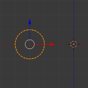
Perfil de extrusión creado.
Next, let’s create a vertical line to specify the distance between spring loops:
Deseleccionar todos los vértices, haciendo clic en un espacio vacío o mediante el atajo Alt-A.
Click Ctrl-RMB twice to create two vertices connected by an edge.
Select both vertices and press S X 0 Return to ensure they have the same X coordinate. (This is necessary to keep the spring’s radius constant.)
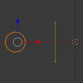
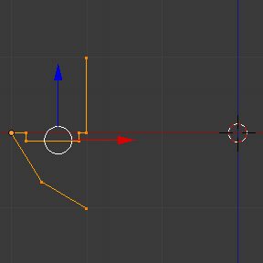
Perfil de guía creado.
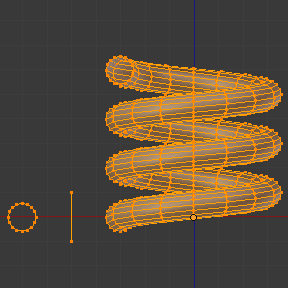
Now, we’re ready to create the spring:
Seleccionar tanto el círculo como la línea, pulsando la tecla A.
Hacer clic en .
Ajustar los Intervalos y las Revoluciones a gusto.
Try changing Axis Z to -1 and see that this makes the spring turn the other way.
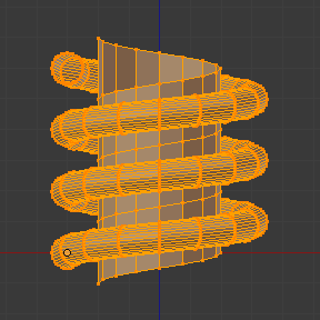
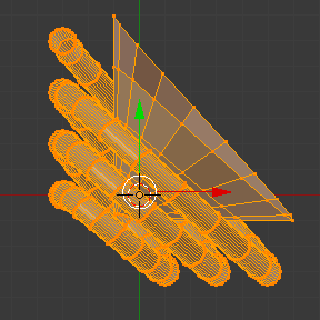
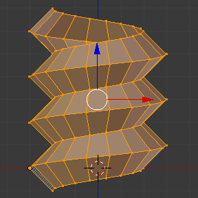
You can get some interesting results by making the Axis diagonal (e.g. keeping Axis Z at -1 and setting Axis X to 1). Notice that each individual spring loop is inclined by 45°, but that after each loop, we still go down vertically (in the direction of the guide line).
|
|
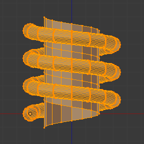
Creación de la rosca de un tornillo
The Screw operator is perfectly suited for creating helices without any gaps between the turns.
Abrir Blender e ingresar al modo Edición para el Cubo predefinido.
Eliminar todos los vértices, presionando kbd: X o: kbd:` Suprimir`.
Cambiar a la vista Frontal (ortogonal) pulsando la tecla Numpad1.
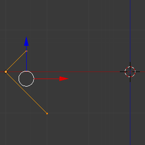
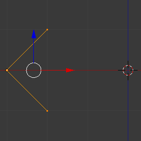
Click Ctrl-RMB three times to create a profile like the one below.
Select the two vertices closest to the global Z axis and press S X 0 Return to ensure they have the same X coordinate.
Seleccionar los tres vértices y hacer clic en .
Ajustar los Intervalos y las Revoluciones a gusto.
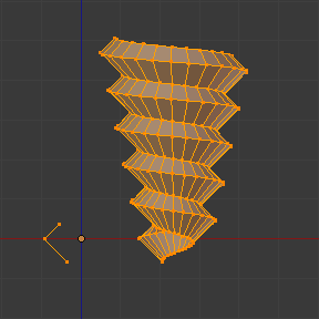
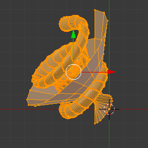
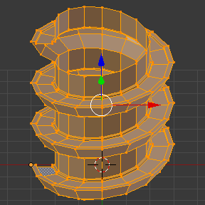
You can also create more interesting shapes, like this spiral «staircase»:
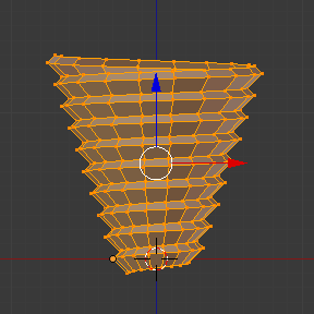
Creación de la punta de un tornillo
Until now, we’ve always made sure that the first and last vertex of the profile have the same X coordinate, thereby keeping the radius of the helix constant. However, nothing stops you from using different X coordinates and having the helix shrink/expand along its height.