Винт (screw)
Ссылка
- Режим (mode):
Режим редактирования (edit mode)
- Меню:
Оператор Screw экструдирует геометрию по спирали. Вы можете использовать его для создания винтов, пружин, ракушек и т. п..
Хотя он похож на модификатор Screw, у него есть несколько важных отличий:
Оператор Screw |
Модификатор Screw |
|---|---|
Работает в мировом пространстве. |
Работает в объектном пространстве. |
Экструдирует только выделенную геометрию. |
Экструдирует всю геометрию. |
Центральную точку можно указать вручную. |
Центральная точка всегда является ориджином объекта. |
Один оборот всегда равен 360°. |
Угол можно выбирать свободно. |
Смещение высоты каждого оборота рассчитывается автоматически на основе геометрии. |
Смещение высоты необходимо указать вручную. |
Каждое вращение может также иметь радиальное смещение от/к центральной оси (опять же определяемое геометрией). |
Радиус остаётся постоянным. |
Как описано выше, оператор Screw автоматически определяет смещение высоты и радиальное смещение, применяемые после каждого оборота. Он делает это, определяя конечные точки открытого профиля – серии соединённых рёбер, которые не образуют замкнутую петлю. Геометрия экструдируется таким образом, что верхняя вершина профиля в одном обороте совпадет с нижней вершиной в следующем.
Наиболее распространённый вариант использования – экструдирование такого открытого профиля. Однако этим вы не ограничены. Пока в выделении есть один открытый профиль – даже если это всего лишь одно независимое ребро – вы также можете экструдировать закрытые профили и даже геометрию с гранями.
Ниже вы можете увидеть несколько примеров.
Использование
Во-первых, убедитесь, что у вашего меша есть открытый профиль. Если вы хотите экструдировать что-то ещё (например, одну или несколько окружностей), вам следует создать открытый профиль рядом с ней.
После этого войдите в режим редактирования и выделите геометрию, которую вы хотите экструдировать, убедившись, что она включает ровно один открытый профиль. Если у вас их меньше или больше – оператор выдаст ошибку «Вам также необходимо выделить цепь связанных вершин.»
Убедитесь, что 3D-Курсор находится в центральной точке, вокруг которой вы собираетесь проворачивать геометрию. Также убедитесь, что вертикальная ось на экране соответствует направлению оси, вокруг которой она должна вращаться. Наиболее распространённым примером является поворот вокруг глобальной оси Z: для этого вам нужно поместить 3D-курсор в начало координат мира и переключиться на ортогональный вид сбоку.
Теперь можно запускать оператор: откройте меню Edge (щёлкнув по нему в заголовке 3D-вьюпорта или нажав Ctrl-E) и нажмите Screw.
Вы можете изменить количество шагов и оборотов на панели настройки последней операции.
Если вы создали открытый профиль только для направления экструдирования (а не потому, что вам нужна его геометрия), вы можете выделить его экструдированные грани, наведя курсор на одну из них и нажав L, а затем удалить их, нажав X или Delete.
Опции (options)
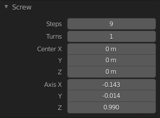
Панель «Screw» (в режиме редактирования).
- Шаги (steps)
Количество выдавливаний, которое необходимо выполнить для каждого оборота в 360°.
- Обороты (turns)
Количество оборотов, которые необходимо создать.
- Центр X, Y, Z (center X, Y, Z)
Координаты центральной точки в мировом пространстве, вокруг которой вращается геометрия. Изначально это местоположение 3D-курсора.
- Ось X, Y, Z (axis X, Y, Z)
Вектор направления, вокруг которого вращается геометрия. Изначально это вертикальная ось экранного пространства (то есть глобальная ось Z при виде сбоку или глобальная ось Y при виде сверху). Инвертируя ось, вы можете переключаться между движением по часовой и против часовой стрелки.
Совет
Вы можете использовать пункт меню «выровнять вид по активному», чтобы выровнять вьюпорт и, следовательно, ось, по определённому элементу в сцене.
Обратите внимание, что ось определяет только то, как геометрия вращается «горизонтально» вокруг центральной точки. Она не определяет, как геометрия движется «вертикально». Вместо этого геометрия всегда движется на расстояние и в направлении, заданном конечными точками открытого профиля, и идет вниз в локальном пространстве объекта.
Примеры
Создание пружины
Сначала давайте создадим окружность, которая будет служить поперечной секцией пружины:
Откройте Blender и удалите куб «по умолчанию».
Добавьте окружность, нажав Shift-A и выбрав .
Установите свойство «положение X» этого нового объекта на -3, а его свойство «вращение X» на 90°.
Войдите в режим редактирования, нажав Tab.
Переключитесь во фронтальный ортографический вид, нажав Numpad1.
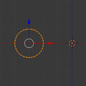
Созданный профиль для экструдирования.
Далее давайте создадим вертикальную линию, чтобы указать расстояние между витками пружины:
Снимите выделение со всех вершин, щёлкнув по пустому месту или нажав Alt-A.
Дважды нажмите Ctrl-ПКМ, чтобы создать две вершины, соединённые ребром.
Выделите обе вершины и нажмите S X 0 Ввод, чтобы убедиться, что они имеют одинаковую координату по X. (Это необходимо для сохранения постоянного радиуса пружины.)
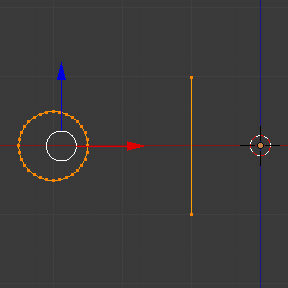
Созданный профиль-ориентир.
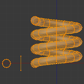
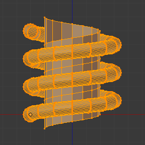
Теперь мы готовы создать пружину:
Выделите окружность и линию, нажав A.
Нажмите или Crtl-E .
Отрегулируйте шаги и обороты как вам нужно.
Попробуйте изменить ось Z на -1 и увидите, что это заставит пружину делать обороты в другую сторону.
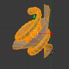
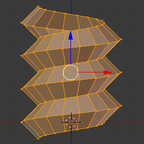
Вы можете получить интересные результаты, сделав ось диагональной (например, сохраняя ось Z на уровне -1 и устанавливая ось X на 1). Обратите внимание, что каждая отдельная петля пружины находится под уклонном в 45°, но после каждой петли мы всё ещё спускаемся вертикально (в направлении линии-ориентира).
|
|
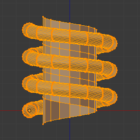
Создание винтового шпинделя
Оператор Screw идеально подходит для создания спиралей без зазоров между витками.
Откройте Blender и войдите в режим редактирования для куба «по умолчанию».
Удалите все вершины, нажав X или Delete.
Переключитесь во фронтальный ортографический вид, нажав Numpad1.
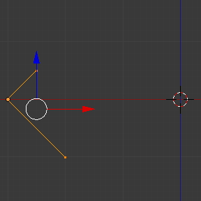
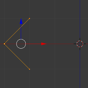
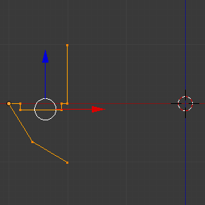
Нажмите Ctrl-ПКМ три раза, чтобы создать профиль, подобный изображённому ниже.
Выделите две вершины, которые находятся ближе к глобальной оси Z, и нажмите S X 0 Ввод, чтобы убедиться, что они имеют одинаковую координату по X.
Выделите все три вершины и нажмите или Crtl-E .
Отрегулируйте шаги и обороты как вам нужно.
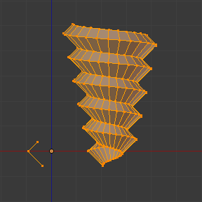
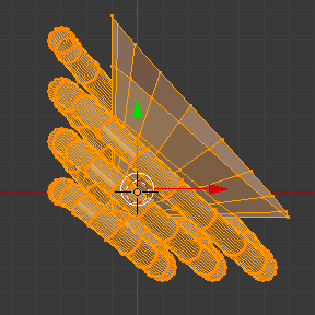
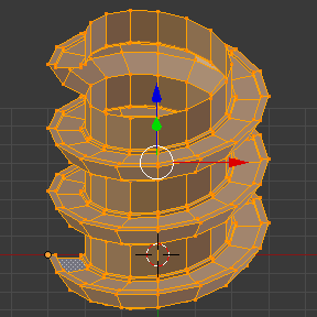
Вы также можете создать более интересные формы, например, эту спиральную «лестницу»:
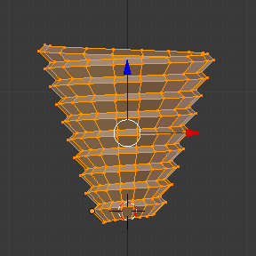
Создание винтового буравчика
До сих пор мы всегда следили за тем, чтобы первая и последняя вершина профиля имели одинаковую координату по X, тем самым сохраняя радиус спирали постоянным. Однако ничто не мешает вам использовать разные координаты X и сжимать/расширять спираль по её высоте.