Opérateurs UV
Blender propose plusieurs façons de cartographier les UV, allant des plus simples qui projettent simplement les sommets du maillage sur un plan aux plus avancées.
Unwrap
Référence
- Éditeur:
3D Viewport
- Mode:
Edit Mode
- Menu:
- Raccourci:
U
Référence
- Éditeur:
Éditeur UV
- Mode:
Edit Mode
- Menu:
- Raccourci:
U
Coupe les faces sélectionnées le long de leurs seams (coutures), les aplatit et les dispose sur la carte UV. Les coordonnées UV existantes sont écrasées. Utile pour les formes organiques.
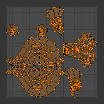
Résultat du dépliage de Suzanne.
Options
Le panneau Adjust Last Operation (Ajuster la dernière opération) permet un contrôle précis de la façon dont le maillage est déplié :
- Method
- Angle Based:
Utilise l’aplatissement basé sur l’angle (ABF). Cette méthode donne une bonne représentation 2D d’un maillage.
- Conformal:
Utilise LSCM (Least Squares Conformal Mapping = Mappage Conforme aux Carrés les plus petits). Cela donne généralement une cartographie UV moins précise que basée sur l’angle, mais fonctionne mieux pour les objets plus simples.
- Minimum Stretch:
Utilise le Scalable Locally Injective Mapping (SLIM). Cela tente d’équilibrer la minimisation de la distorsion de zone et la minimisation de la distorsion angulaire.
- Fill Holes
Remplir virtuellement les trous dans le maillage avant de le déplier, pour mieux éviter les chevauchements et préserver la symétrie.
- Use Subdivision Surface
Utiliser les nouvelles positions des sommets calculées par le Modificateur Subdivision Surface (plutôt que les positions d’origine avant l’exécution des modificateurs).
- Correct Aspect
Ajuste la cartographie UV pour tenir compte du rapport d’aspect de l’image associée au matériau. Cela garantit que les UV sont correctement mis à l’échelle lorsqu’ils sont dépliés sur des textures non carrés.
Pour que cette option fonctionne, le maillage doit avoir un matériau avec un Image Texture node et ce nœud doit être sélectionné dans le Shader Editor.
- Iterations Minimum Stretch
Nombre d’itérations pour la méthode Minimum Stretch, où chaque itération réduit davantage la distorsion.
- No Flip Minimum Stretch
Interdire le retournement des faces. L’autoriser entraîne parfois moins de distorsion lorsqu’il y a des pins.
- Importance Weights Minimum Stretch
Vous permet de spécifier un groupe de sommets pour influencer manuellement la taille de certaines faces dans la carte UV. Les faces situées autour de sommets de poids élevé occuperont plus d’espace dans la carte UV que celles situées autour de sommets de poids faible.
En activant cette option, deux autres apparaissent :
- Weight Group
Le nom du groupe de sommets à utiliser.
- Weight Factor
Un facteur global par lequel multiplier tous les poids. Un nombre plus élevé entraînera une différence plus exagérée entre les zones de poids élevé et les zones de poids faible.
- Margin Method
La signification du paramètre Margin, qui détermine la taille de l’espace vide entre les îlots UV.
- Scaled
Margin est une mesure plus ou moins arbitraire sans rapport direct avec la taille des îlots UV ou la texture.
- Add
Comme ci-dessus, mais sans le facteur d’échelle calculé en interne.
- Fraction
Margin est une fraction des limites UV. Cela signifie que si vous avez une texture de 1 024 x 1 024 et que vous définissez Margin sur 1/1 024, chaque îlot UV aura une marge de 1 pixel autour (et les îlots ne seront pas à moins de 2 pixels les uns des autres).
- Margin
Combien d’espace vide laisser entre les îlots. Contrôlé par la Margin Method.
Smart UV Project
Référence
- Éditeur:
Vue 3D, Éditeur UV
- Mode:
Edit Mode
- Menu:
- Raccourci:
U
Examine les angles entre les faces sélectionnées, les coupe le long des arêtes vives, puis projette chaque groupe de faces séparé le long de sa normale moyenne et le dispose sur la carte UV. Vous pouvez également configurer des seams pour une coupe supplémentaire. C’est une bonne méthode pour, par exemple, les objets mécaniques ou l’architecture.
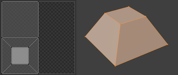
Projet Smart UV sur une pyramide tronquée.
Options
Le panneau Adjust Last Operation (Ajuster la dernière opération) permet un contrôle précis de la façon dont le maillage est déplié :
- Angle Limit
L’angle maximum autorisé entre les normales des faces adjacentes avant qu’elles ne soient séparées les unes des autres. Une limite basse créera de nombreux petits îlots UV avec peu de distorsion, tandis qu’une limite élevée créera quelques grands îlots avec potentiellement plus de distorsion.
- Margin Method
La signification du paramètre Island Margin, qui détermine la taille de l’espace vide entre les îlots UV.
- Scaled
Island Margin est une mesure plus ou moins arbitraire sans rapport direct avec la taille des îlots UV ou la texture.
- Add
Comme ci-dessus, mais sans le facteur d’échelle calculé en interne.
- Fraction
Island Margin est une fraction du carré de l’unité UV. Cela signifie que si vous avez une texture de 1 024 x 1 024 et que vous définissez Island Margin sur 1/1 024, chaque îlot UV aura une marge de 1 pixel autour d’elle (et les îlots ne seront pas à moins de 2 pixels les uns des autres).
- Rotation Method
- Axis-aligned
Rotation automatique pour éviter de perdre de l’espace.
- Axis-aligned (Horizontal)
Faire pivoter les îlots pour les aligner horizontalement.
- Axis-aligned (Vertical)
Faire pivoter les îlots pour les aligner verticalement.
- Island Margin
Combien d’espace vide laisser entre les îlots. Contrôlé par la Margin Method.
- Area Weight
Avec une valeur de 0, le vecteur de projection de chaque groupe de faces est simplement la moyenne de ses normales de face. Avec une valeur de 1, c’est une moyenne pondérée en utilisant les zones des faces. D’autres valeurs sont un mélange entre les deux.
- Correct Aspect
Ajuste la cartographie UV pour tenir compte du rapport d’aspect de l’image associée au matériau. Cela garantit que les UV sont correctement mis à l’échelle lorsqu’ils sont dépliés sur des textures non carrés.
Pour que cette option fonctionne, le maillage doit avoir un matériau avec un Image Texture node et ce nœud doit être sélectionné dans le Shader Editor.
- Scale to Bounds
Étire la carte UV résultante pour remplir la texture complète.
Lightmap Pack
Référence
- Éditeur:
Vue 3D, Éditeur UV
- Mode:
Edit Mode
- Menu:
- Raccourci:
U
Place chaque face sélectionnée séparément sur la carte UV. Les lightmaps sont couramment utilisées pour intégrer des informations d’éclairage dans une texture à utiliser dans le rendu en temps réel. En tant que telles, elles donnent la priorité à l’utilisation d’autant de texture que possible, ce qui entraîne généralement une carte UV déconnectée et déformée qui ne conviendrait pas au travail de texturation manuel.
Options
Le panneau Adjust Last Operation (Ajuster la dernière opération) permet un contrôle précis de la façon dont le maillage est déplié :
- Selection
- Selected Faces
Déplie uniquement les faces sélectionnées.
- All Faces
Déplie tout le maillage.
- Share Texture Space
Vous pouvez utiliser Édition multi-objets pour générer des cartes UV pour plusieurs maillages en même temps. Lorsque Share Texture Space (Partager l’espace de texture) est activé, les cartes UV ne se chevauchent pas, de sorte que vous puissiez ensuite utiliser la même texture lightmap pour tous les maillages.
- New UV Map
Crée une nouvelle carte UV au lieu d’écraser celle actuellement sélectionnée. Voir les UV Maps.
- Pack Quality
Des valeurs plus élevées génèrent une carte UV qui gaspille moins d’espace (mais qui prend également plus de temps à calculer).
- Margin
Combien d’espace vide laisser entre les faces dans la carte UV.
Follow Active Quads
Référence
- Éditeur:
Vue 3D, Éditeur UV
- Mode:
Edit Mode
- Menu:
- Raccourci:
U
Commence à partir du quad actif et attache récursivement ses quads de maillage sélectionnés voisins à son quad UV préexistant. Les faces non quadruples sont ignorées.
Note
Étant donné que la disposition UV du quad actif reste inchangée, vous souhaiterez généralement vous assurer qu’il a la même forme dans la carte UV que sur le maillage avant d’exécuter ce dépliage (par exemple en exécutant un autre type de dépliage uniquement sur cette face). Sinon, la distorsion se propagera à toutes les autres faces.
Note
La carte UV résultante peut sortir des limites. Vous pouvez résoudre ce problème en le réduisant manuellement ou en utilisant Pack Islands.
Options
Le panneau Adjust Last Operation (Ajuster la dernière opération) permet un contrôle précis de la façon dont le maillage est déplié :
- Edge Length Mode
Comment calculer les longueurs des bords UV pour les quads nouvellement attachés.
- Even
Donne à chaque nouveau bord UV la même longueur que le bord UV qu’il étend, quelle que soit sa longueur sur le maillage.
- Length
Donne à chaque nouveau bord UV une longueur proportionnelle à sa longueur sur le maillage.
- Length Average
Donne à chaque nouveau bord UV une longueur proportionnelle à la longueur moyenne du bord dans sa boucle d’arêtes sur le maillage.
Cube Projection
Référence
- Éditeur:
Vue 3D, Éditeur UV
- Mode:
Edit Mode
- Menu:
- Raccourci:
U
Projette chaque face sélectionnée sur le côté le plus approprié d’un cube virtuel, puis place tous ces côtés dans la carte UV, en se chevauchant. Si vous ne souhaitez pas qu’ils se chevauchent, vous pouvez Pack Islands.
Le cube est centré sur le Nœud Transform Pivot Point et aligné sur les axes locaux du maillage.
Options
Le panneau Adjust Last Operation (Ajuster la dernière opération) permet un contrôle précis de la façon dont le maillage est déplié :
- Cube Size
La taille du cube sur lequel projeter.
- Correct Aspect
Ajuste la cartographie UV pour tenir compte du rapport d’aspect de l’image associée au matériau. Cela garantit que les UV sont correctement mis à l’échelle lorsqu’ils sont dépliés sur des textures non carrés.
Pour que cette option fonctionne, le maillage doit avoir un matériau avec un Image Texture node et ce nœud doit être sélectionné dans le Shader Editor.
- Clip to Bounds
Déplace tous les UV hors limites vers la bordure la plus proche.
- Scale to Bounds
Étire la carte UV résultante pour remplir la texture complète.
Cylinder Projection
Référence
- Éditeur:
Vue 3D, Éditeur UV
- Mode:
Edit Mode
- Menu:
- Raccourci:
U
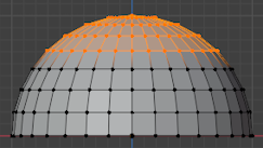
Projette les faces sélectionnées sur un cylindre virtuel, puis déroule ce cylindre. Le cylindre est centré sur le Nœud Transform Pivot Point, qui correspond normalement à la position moyenne des faces sélectionnées; cependant, vous pouvez également le déplacer vers un autre endroit en utilisant par ex. le 3D Cursor.
Options
Le panneau Adjust Last Operation (Ajuster la dernière opération) permet un contrôle précis de la façon dont le maillage est déplié :
- Direction, Align
La direction de l’axe central du cylindre.
- View on Equator
Utiliser un axe perpendiculaire à la direction de visualisation dans la fenêtre 3D. Si Align est Polar ZX, utilise l’axe vertical du plan de visualisation; s’il s’agit d’un Polar ZY, utilise l’axe horizontal.
- View on Poles
Utiliser un axe parallèle à la direction de visualisation dans la fenêtre 3D. En fonction de Align, le cylindre pivotera de 90° autour de son axe et la carte UV sera décalée horizontalement d’un quart.
- Align to Object
Utiliser l’axe Z local de l’objet. En fonction de Align, le cylindre pivotera de 90° autour de son axe et la carte UV sera décalée horizontalement d’un quart.
- Pole (Pôle)
Comment gérer les sommets situés sur l’axe central du cylindre.
- Pinch
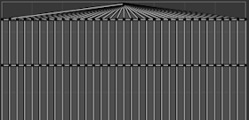
Place toutes les versions UV du sommet à la même coordonnée U. Cela a tendance à entraîner des faces UV fortement déformées.
- Fan
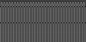
Place chaque version UV du sommet à une coordonnée U qui minimise la distorsion.
- Preserve Seams
Coupe le maillage le long de ses coutures avant de le projeter.
- Radius
La moitié de la hauteur du cylindre (c’est-à-dire non pas son rayon; nous utilisons uniquement le cylindre pour la projection, donc son rayon n’a pas d’importance).
- Correct Aspect
Ajuste la cartographie UV pour tenir compte du rapport d’aspect de l’image associée au matériau. Cela garantit que les UV sont correctement mis à l’échelle lorsqu’ils sont dépliés sur des textures non carrés.
Pour que cette option fonctionne, le maillage doit avoir un matériau avec un Image Texture node et ce nœud doit être sélectionné dans le Shader Editor.
- Clip to Bounds
Déplace tous les UV hors limites vers la bordure la plus proche.
- Scale to Bounds
Étire la carte UV résultante pour remplir la texture complète.
Sphere Projection
Référence
- Éditeur:
Vue 3D, Éditeur UV
- Mode:
Edit Mode
- Menu:
- Raccourci:
U
Projette les faces sélectionnées sur une sphère virtuelle, puis aplatit cette sphère un peu comme une carte du monde : les lignes de latitude verticales et les lignes de longitude régulièrement espacées. C’est utile pour texturer des formes sphériques telles que des yeux ou des planètes.
La sphère est centrée sur le Nœud Transform Pivot Point, qui correspond normalement à la position moyenne des faces sélectionnées; cependant, vous pouvez également le déplacer vers un autre endroit en utilisant par ex. le 3D Cursor.
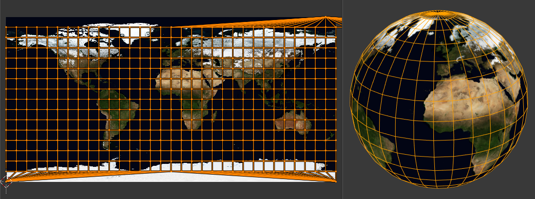
Utilisation d’une image équirectangulaire avec une projection Sphère.
Options
Le panneau Adjust Last Operation (Ajuster la dernière opération) permet un contrôle précis de la façon dont le maillage est déplié :
- Direction, Align
La direction de l’axe vertical de la sphère.
- View on Equator
Utiliser un axe perpendiculaire à la direction de visualisation dans la fenêtre 3D. Si Align est Polar ZX, utilise l’axe vertical du plan de visualisation; s’il s’agit d’un Polar ZY, utilise l’axe horizontal.
- View on Poles
Utilise un axe parallèle à la direction de visualisation dans la fenêtre 3D. En fonction d”Align, la sphère pivotera de 90° autour de son axe vertical et la carte UV sera décalée d’un quart horizontalement.
- Align to Object
Utilise l’axe Z local de l’objet. En fonction d”Align, la sphère pivotera de 90° autour de son axe vertical et la carte UV sera décalée d’un quart horizontalement.
- Pole (Pôle)
Comment gérer les sommets situés sur l’axe vertical de la sphère. (Voir Cylinder Projection pour un exemple.)
- Pinch
Place toutes les versions UV du sommet à la même coordonnée U. Cela a tendance à entraîner des faces UV fortement déformées.
- Fan
Place chaque version UV du sommet à une coordonnée U qui minimise la distorsion.
- Preserve Seams
Coupe le maillage le long de ses coutures avant de le projeter.
- Correct Aspect
Ajuste la cartographie UV pour tenir compte du rapport d’aspect de l’image associée au matériau. Cela garantit que les UV sont correctement mis à l’échelle lorsqu’ils sont dépliés sur des textures non carrés.
Pour que cette option fonctionne, le maillage doit avoir un matériau avec un Image Texture node et ce nœud doit être sélectionné dans le Shader Editor.
- Clip to Bounds
Déplace tous les UV hors limites vers la bordure la plus proche.
- Scale to Bounds
Étire la carte UV résultante pour remplir la texture complète.
Project from View
Référence
- Éditeur:
3D Viewport
- Mode:
Edit Mode
- Menu:
- Raccourci:
U
Projette les faces sélectionnées sur le plan de la vue. La carte UV devient essentiellement une image filaire du maillage, prise dans la fenêtre 3D sous l’angle de vue actuel. Utilisez cette option si vous utilisez l’image d’un objet réel comme texture. Il en résulte un étirement dans les zones où le modèle s’éloigne de vous.
Options
Le panneau Adjust Last Operation (Ajuster la dernière opération) permet un contrôle précis de la façon dont le maillage est déplié :
- Orthographic (Orthographique)
Utilise une projection Orthographique au lieu de Perspective.
- Camera Bounds
Mappe les bordures de l’image qui serait rendue par la caméra actuelle sur les bordures de la carte UV. Cette option n’a d’effet que lors de la visualisation de la scène via la caméra; voir Affichage de la caméra active.
- Correct Aspect
Ajuste la cartographie UV pour tenir compte du rapport d’aspect de l’image associée au matériau. Cela garantit que les UV sont correctement mis à l’échelle lorsqu’ils sont dépliés sur des textures non carrés.
Pour que cette option fonctionne, le maillage doit avoir un matériau avec un Image Texture node et ce nœud doit être sélectionné dans le Shader Editor.
- Clip to Bounds
Déplace tous les UV hors limites vers la bordure la plus proche.
- Scale to Bounds
Étire la carte UV résultante pour remplir la texture complète.
Project from View (Bounds)
Référence
- Éditeur:
3D Viewport
- Mode:
Edit Mode
- Menu:
- Raccourci:
U
Identique à Project from View, mais avec l’option Scale to Bounds (Échelle aux limites) activée par défaut.
Reset
Référence
- Éditeur:
Vue 3D, Éditeur UV
- Mode:
Edit Mode
- Menu:
- Raccourci:
U
Réinitialise la disposition UV de chaque face sélectionnée pour remplir toute la zone UV.
