Mesh Structure
With meshes, everything is built from three basic elements: vertices, edges and faces.

Приклад структури сіті.
Vertices – Вершини
The most elementary part of a mesh is the vertex (vertices plural) which is a single point or position in 3D space. Vertices are represented in the 3D Viewport in Edit Mode as small dots. The vertices of an object are stored as an array of coordinates.
Порада
Do not mistake the object origin for a vertex. It may look similar, but it is bigger and cannot be selected.
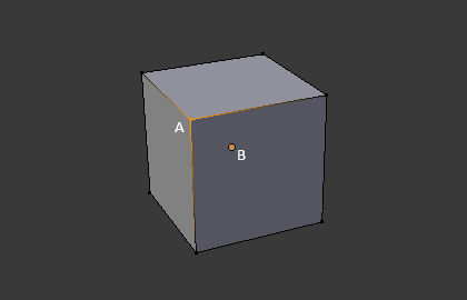
Вершина позначена як «A»; точка початку об’єкта позначена як «B».
Edges – Краї
An edge always connects two vertices by a straight line. The edges are the «wires» you see when you look at a mesh in wireframe view. They are usually invisible on the rendered image. They are used to construct faces.
Обличчя
Faces are used to build the actual surface of the object. They are what you see when you render the mesh. If this area does not contain a face, it will simply be transparent or nonexistent in the rendered image.
A face is defined as the area between either three (triangles), four (quadrangles) or more (n-gons) vertices, with an edge on every side. The faces are often abbreviated to tris, quads & n-gons.
Triangles are always flat and therefore easy to calculate. On the other hand, quadrangles «deform well» and are therefore preferred for animation and subdivision modeling.
Нормалі
У геометрії нормаль – це напрямок або лінія, що є перпендикулярною до чогось, типово, трикутника або поверхні, але може також бути відносно лінії, дотичної лінії для точки на кривій або дотичної площини для точки на поверхні.
Normals help to determine the shading of the mesh among other things.
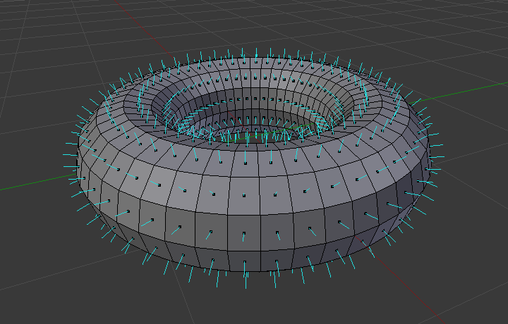
Візуалізація нормалей граней тора.
In the figure above, each blue line represents the normal for a face on the torus. The lines are each perpendicular to the face on which they lie. The visualization can be activated, in Edit Mode, in the Mesh Display Viewport Overlays panel.
Відтінювання
Surface normals play a fundamental role in determining how light interacts with 3D objects and thus greatly influence the shading of those objects. Normals can be shaded smooth or flat.
When a mesh uses flat shading, the faces are rendered and displayed uniformly. This is usually desirable for objects with flat surfaces such as a cube or pyramid.
When a mesh uses smooth shading, the normals are interpolated across the vertices of a polygonal mesh, smooth transitions between adjacent polygons can be achieved, resulting in a more realistic appearance.
By default face normals have flat shading however, this can be adjusted either for the whole object or per face.
To adjust the shading of the whole object, use:
Згладжене Відтінення – Shade Smooth – To mark the whole object as smooth.
Shade Auto Smooth – To mark portions of the object as smooth.
To revert to flat shading, use Плоске Відтінення – Shade Flat.
The shading of objects can also be adjusted per face, edge, or vertex.
Кастомні Розділені Нормалі – Custom Split Normals
Custom split normals are a way to tweak/fake shading by pointing normals towards other directions than the default, auto-computed ones. It is mostly used in game development, where it helps counterbalance some issues generated by low-poly objects (the most common examples are low-poly trees, bushes, grass, etc. and the „rounded“ corners).
Blender supports custom normals on a „smooth fan“ base, defined as a set of neighbor face corners sharing the same vertex and „linked“ by smooth edges. This means you can have normals per face corners, per a set of neighbor face corners, or per vertex.
Custom split normal data is stored as the custom_normal
Attribute on the face corner Domain.
Порада
The computation of custom split normals can be disabled to improve performance. This option can be found in the Simplify Rendering Settings.
Free Normals
Free normals are a type of custom normal stored directly as direction vectors in object space. Unlike traditional custom normals, which are defined relative to the surrounding geometry (known as tangent or corner fan space), free normals are independent of mesh topology and do not rely on smooth groups or edge connectivity.
Because they are simple vectors, free normals are:
Efficient: Fast to evaluate, significantly improving viewport performance compared to tangent space normals.
Lightweight: Require less memory, especially beneficial for dense or heavily instanced meshes.
Static: They do not automatically update when the mesh is deformed (e.g. through modifiers or animations), so they are best suited for static geometry or cases where performance is critical.
Free normals can be assigned using the Set Mesh Normal Node in Free mode, and stored on the vertex, face, or face corner domain depending on the desired granularity.
Редагування Кастомних Розділених Нормальней – Editing Custom Split Normals
Посилання
- Режим:
Режим Редагування
- Меню:
«Сіть > Нормалі» –
- Скорочення:
Alt-N
There are a number of tools for editing custom split normals. The custom normal mesh edit tools can affect all normals (the default), or only selected ones. To select a custom normal associated with a particular vertex and face:
Зробіть режим вибрання елементів одночасно Вершин і Граней (використайте Shift-LMB для вмикання ще й другого).
Select one or more vertices, then select a face. This can be repeated to select more vertices and a different face and so on. It is easiest to see the effect of these tools if you turn on the Edit Mode Overlays option Display vertex-per-face normals as lines.
Дивись також
Імпортування Кастомних Розділених Нормалей – Importing Custom Split Normals
Some tools, particularly those used in CAD, tend to generate irregular geometry when tessellating their objects into meshes (very thin and long triangles, etc.). Auto-computed normals on such geometry often gives bad artifacts, so it is important to be able to import and use the normals as generated by the CAD tool itself.
Примітка
Currently, only the FBX Importer and Alembic Importer are capable of importing custom normals.
Topology – Топологія
Петлі – Loops
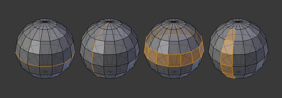
Петлі ребер та граней.
Петлі ребер та граней є наборами граней або ребер, що формують безперервні «петлі», як показано на Ілюстрації Петлі ребер та граней..
In the image above, loops that do not end in poles are cyclic (1 and 3). They start and end at the same vertex and divide the model into two partitions. Loops can be a quick and powerful tool to work with specific, continuous regions of a mesh and are a prerequisite for organic character animation. For a detailed description of how to work with loops in Blender, see: Вибрати Петлі – Select Loops.
Примітка
Note that loops (2 and 4) do not go around the whole model. Loops stop at so-called poles because there is no unique way to continue a loop from a pole. Poles are vertices that are connected to either three, five, or more edges. Accordingly, vertices connected to exactly one, two or four edges are not poles.
Петлі Ребер – Edge Loops
Loops (1 and 2) in Fig. Петлі ребер та граней. are edge loops. They connect vertices so that each one on the loop has exactly two neighbors that are not on the loop and placed on both sides of the loop (except the start and end vertex in case of poles).
Edge loops are an important concept especially in organic (subsurface) modeling and character animation. When used correctly, they allow you to build models with relatively few vertices that look very natural when used as subdivision surfaces and deform very well in animation.
Take Fig. Петлі ребер та граней. in organic modeling as an example: the edge loops follow the natural contours and deformation lines of the skin and the underlying muscles. The loops are denser in areas that deform more when the character moves, for example at the shoulders or knees.
Further details on working with edge loops can be found in Вибрати Петлі – Select Loops.
Петлі Граней – Face Loops
These are a logical extension of edge loops in that they consist of the faces between two edge loops, as shown in loops (3 and 4) in Fig. Петлі ребер та граней.. Note that for non-circular loops (4) the faces containing the poles are not included in a face loop.
Більше деталей щодо роботи з петлями граней можна знайти у Face Loop Selection.
Полюси – Poles
Дивіться N-poles & E-poles.
Не-Розгортне – Non-Manifold
Дивіться Non-manifold.