Керувальні Точки – Control Points
Видавити Криву та Перемістити – Extrude Curve and Move
Посилання
- Режим:
Режим Редагування
- Меню:
- Скорочення:
E
Extruding is the main way of adding new control points to a surface. It’s not possible to do this directly as would be the case with Curves.
Start by selecting a complete border of the surface grid. Then press E to duplicate the control points, and move the mouse to bring them to the desired position. Finally, click LMB to confirm. (Alternatively, click RMB or press Esc to cancel the move and keep the new control points at their original position.)
Приклад
First, we select a border control point and expand the selection to the complete row using Вибрати Ряд Керувальних Точок – Select Control Point Row.
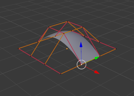
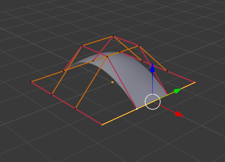
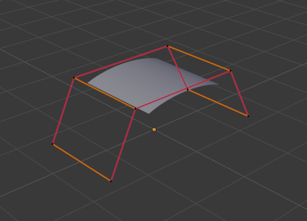
Then, we extrude a few times:
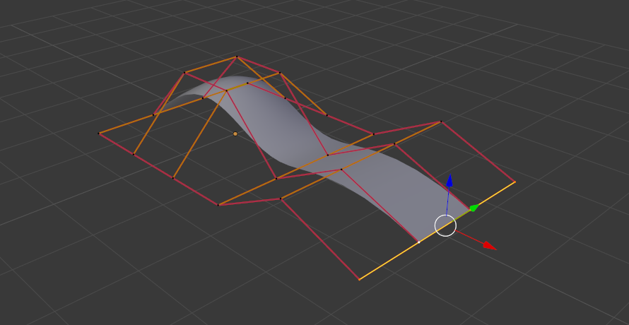
Control points extruded twice
Зробити Сегмент – Make Segment
Посилання
- Режим:
Режим Редагування
- Меню:
- Скорочення:
F
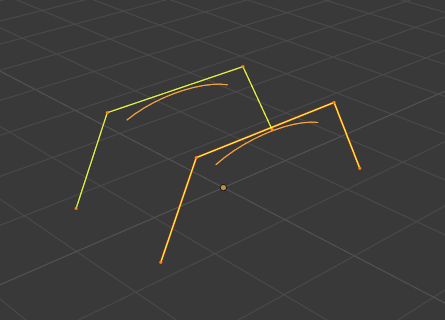
While this operator sounds like it creates a single segment (grid line) between two control points, it’s really more similar to Bridge Edge Loops for meshes: it bridges the gap between two disjoint surfaces by creating as many new segments as necessary. Simply select a border row (or column) in each surface, then press F to connect those borders.
Note that the two surfaces need to be part of the same Surface object. If you have two separate objects, these first need to be combined into one using Сполучення – Join. Also, the borders to connect must have the same number of control points.
Приклад
The images below show bridging of two «surfaces» consisting of just a curve, but it’s also possible to connect sheets.
Smooth – Згладження
Посилання
- Режим:
Режим Редагування
- Меню:
Moves the selected control points to give the surface a smoother appearance.
Гачки – Hooks
Посилання
- Режим:
Режим Редагування
- Меню:
- Скорочення:
Ctrl-H
Adds a Модифікатор «Гачок» – Hook Modifier that makes the selected control points follow a particular object or bone.
Зробити Приріднення до Вершин – Make Vertex Parent
Посилання
- Режим:
Режим Редагування
- Меню:
- Скорочення:
Ctrl-P
Creates a parent-child relationship that makes a particular object follow the selected control point(s).
While in Edit Mode, select another object by either clicking it with Ctrl-LMB in the 3D Viewport or by selecting it the Outliner. Then, select one or three control points of the surface and press Ctrl-P. Parenting an object to three control points will make it follow their averaged position.